Most innovative companies for 01/09/2024 (new inventions)
Exciting new inventions from Qualcomm Incorporated, Samsung Electronics Co., Ltd., Micron Technology, Inc. And Amazon Technologies, Inc.
This is a weekly article summarizing a handful of inventions from the most innovative companies in the world. The summaries are created by an A. I. and proof-read by a human before publication. Attempts are made to ensure accuracy of the descriptions, but it is very much a work in progress. Each invention description is preceeded by a poem about the invention that is written by the A. I. I have found the limerick is actually quite good at explaining the invention in simple terms. Enjoy!
Amazon Technologies, Inc.
"Amazon Patents Robotic Picking Assemblies with Adjustable Flow Rates for Efficient Item Grasping"
What is this invention?
Robotic picking assemblies with different concurrent flow rates
In robotic picking, they show finesse
Different flows, they can surely impress
With suction cups and mesh filters in play
Grasping items in their own unique way
Concurrent rates, causing no distress!
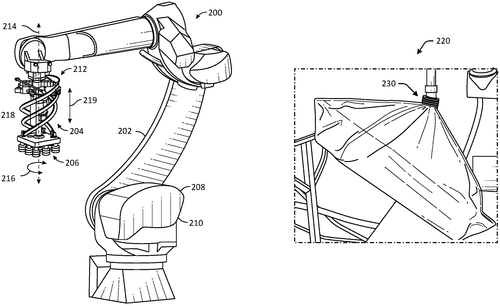
In its latest patent, Amazon Technologies, Inc. introduces a groundbreaking innovation in the field of robotic picking assemblies. This system, with its different concurrent flow rates, aims to enhance efficiency and flexibility in automated processes. The patent describes a picking assembly that is connected to a vacuum system. This assembly consists of three suction cup units, each with its own unique flow rate and mesh filter. The first suction cup assembly has a specific flow rate, while the second and third assemblies have a different but identical flow rate. These suction cups, along with their corresponding mesh filters, work in tandem to grasp items utilizing the first and second flow rates. On the surface, this technology seems promising, as it could potentially revolutionize the world of warehouse automation. The ability to adjust the flow rate depending on the specific item being picked could greatly improve the picking process and increase overall productivity. However, as with any patent, we must remain pragmatic in our evaluation. Although Amazon is known for its innovative endeavors, not all patents translate into marketable products. It will be interesting to see if Amazon can successfully bring this invention to fruition and, if so, how it will compete with existing robotic picking systems on the market. For instance, competitors like KUKA and ABB have established themselves as leaders in the automation industry, offering a wide range of robotic solutions. It remains to be seen whether Amazon's robotic picking assembly with different concurrent flow rates can provide a significant advantage over these established players. Beyond warehousing, this technology may find potential applications in industries that require precise manipulation and handling of fragile objects. The ability to modulate the flow rate could allow for greater delicacy in grasping and moving delicate items such as electronics or medical equipment. In conclusion, the patented robotic picking assembly by Amazon Technologies, Inc. sparks excitement in terms of its potential to revolutionize the automated picking process. However, only time will tell if this innovation will make it to the market and if it can effectively compete with established industry players. What are your thoughts on this innovation? Do you believe Amazon's invention has the potential to disrupt the automation industry? Share your insights and opinions in the comments below.
Abstract
Systems, methods, and computer-readable media are disclosed for robotic picking assemblies with different concurrent flow rates. In one embodiment, an example system may include a picking assembly coupled to a vacuum system. The picking assembly may include a first suction cup assembly having a first flow rate, the first suction cup assembly including a first suction cup and a first mesh filter disposed in the first suction cup, a second suction cup assembly having a second flow rate, the second suction cup assembly including a second suction cup and a second mesh filter disposed in the second suction cup, and a third suction cup assembly having the second flow rate, the third suction cup assembly including a third suction cup and a third mesh filter disposed in the third suction cup. The picking assembly may grasp items based on the first flow rate and the second flow rate. Systems, methods, and computer-readable media are disclosed for robotic picking assemblies with different concurrent flow rates. In one embodiment, an example system may include a picking assembly coupled to a vacuum system. The picking assembly may include a first suction cup assembly having a first flow rate, the first suction cup assembly including a first suction cup and a first mesh filter disposed in the first suction cup, a second suction cup assembly having a second flow rate, the second suction cup assembly including a second suction cup and a second mesh filter disposed in the second suction cup, and a third suction cup assembly having the second flow rate, the third suction cup assembly including a third suction cup and a third mesh filter disposed in the third suction cup. The picking assembly may grasp items based on the first flow rate and the second flow rate.
US Patent 11865727
QUALCOMM Incorporated
"QUALCOMM's Inventive Compressed Memory System Enhances Processor-Based Efficiency"
What is this invention?
Priority-based cache-line fitting in compressed memory systems of processor-based systems
In a world where processors prevail,
A memory system sets the trail,
Partitioning and selecting,
Compressing and detecting,
Cache lines packed, innovation shall not fail.
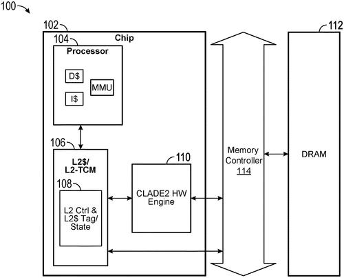
QUALCOMM Incorporated has recently filed a patent for a groundbreaking compressed memory system. This system boasts a memory partitioning circuit that can split a memory region into different data regions with varying priority levels. Alongside this, the system also incorporates a cache line selection circuit, a compression circuit, and a cache line packing circuit. The cache line selection circuit is responsible for handpicking a cache line from a high priority data region and another from a low priority data region. These cache lines are then compressed by the compression circuit, resulting in a first and a second compressed cache line. To further optimize the memory space, the cache line packing circuit compactly arranges the compressed cache lines. Specifically, the first compressed cache line is written to a larger predetermined portion, while the second cache line or a portion of the second compressed cache line is written to a smaller predetermined portion within the candidate compressed cache line. While this patent reveals an innovative approach to memory management in processor-based systems, it remains to be seen whether QUALCOMM will bring this technology to the consumer market. Competing companies such as Intel and AMD already have their own memory management solutions, and it is unclear how QUALCOMM's compressed memory system will stack up against these established offerings. Nevertheless, the potential applications for such a technology are captivating. By efficiently compressing and arranging cache lines based on priority, this system could potentially enhance the performance and overall efficiency of processor-based systems. It has implications for a broad range of industries, including data centers, artificial intelligence, and edge computing, where memory management plays a critical role in maximizing processing power. However, the practicality of implementing a compressed memory system with such complex circuitry and partitioning remains uncertain. The question remains: Will QUALCOMM be able to overcome the challenges and turn this patent into a tangible product for consumers? Let us know your thoughts in the comments below. How do you think a compressed memory system like this could revolutionize processor-based systems?
Abstract
A compressed memory system of a processor-based system includes a memory partitioning circuit for partitioning a memory region into data regions with different priority levels. The system also includes a cache line selection circuit for selecting a first cache line from a high priority data region and a second cache line from a low priority data region. The system also includes a compression circuit for compressing the cache lines to obtain a first and a second compressed cache line. The system also includes a cache line packing circuit for packing the compressed cache lines such that the first compressed cache line is written to a first predetermined portion and the second cache line or a portion of the second compressed cache line is written to a second predetermined portion of the candidate compressed cache line. The first predetermined portion is larger than the second predetermined portion. A compressed memory system of a processor-based system includes a memory partitioning circuit for partitioning a memory region into data regions with different priority levels. The system also includes a cache line selection circuit for selecting a first cache line from a high priority data region and a second cache line from a low priority data region. The system also includes a compression circuit for compressing the cache lines to obtain a first and a second compressed cache line. The system also includes a cache line packing circuit for packing the compressed cache lines such that the first compressed cache line is written to a first predetermined portion and the second cache line or a portion of the second compressed cache line is written to a second predetermined portion of the candidate compressed cache line. The first predetermined portion is larger than the second predetermined portion.
US Patent 11868244
QUALCOMM Incorporated
"Qualcomm's New Patent Revolutionizes Graphics Processing with Dynamic Shading Rate Mapping"
What is this invention?
Density driven variable rate shading
In the realm of graphics, they say,
Devices and methods pave the way.
An apparatus, quite grand,
Obtains visibility, you understand,
Mapping density to shades, we convey.
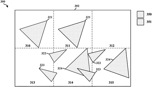
In a recent patent application filed by QUALCOMM Incorporated, new methods and devices for graphics processing are the focus of attention. The patent describes an apparatus, which could be a GPU or a CPU, that aims to enhance graphics rendering capabilities. While the technical details in the patent are complex, it essentially relates to optimizing the shading of graphics elements in a frame. The apparatus first obtains visibility information for a set of primitives, which are the basic building blocks of the graphics, in at least one frame. The frame is divided into multiple bins, with each bin potentially containing one or more of these primitives. To improve the rendering process, the apparatus then creates a density map based on the visibility information, which determines the amount of primitives present in each bin. Finally, by mapping the density data for each bin, the apparatus can determine the appropriate shading rate for each bin. If successfully implemented, this technology has the potential to significantly enhance graphics processing capabilities. By intelligently allocating shading resources based on the density of primitives in each bin, the apparatus could render complex scenes with improved efficiency and visual quality. Gaming and virtual reality applications could benefit from more realistic and immersive graphics, while industries such as architecture and design might find it useful for rendering complex models. However, it's important to note that a patent is not a guaranteed indication that a product will be developed. Many patents never make it to market due to a variety of reasons, such as technical limitations, market demand, or competition from existing solutions. In the realm of graphics processing, there are already established players that provide similar optimization techniques, such as NVIDIA's Turing architecture or AMD's RDNA technology. While this patent demonstrates QUALCOMM's innovative approach to graphics processing, the ultimate question remains: will this technology be developed into a product that consumers can benefit from? What are your thoughts on potential applications for this optimization technique? Let us know in the comments below.
Abstract
Aspects presented herein relate to methods and devices for graphics processing including an apparatus, e.g., a GPU or a CPU. The apparatus may obtain visibility information for a set of primitives in at least one frame associated with the graphics processing, where the at least one frame includes a plurality of bins, such that at least one bin of the plurality of bins includes at least one primitive of the set of primitives. The apparatus may also configure a density map based on the visibility information for the set of primitives, where the density map includes density data associated with an amount of the set of primitives in each of the plurality of bins. Further, the apparatus may map the density data for each of the plurality of bins to a shading rate for each of the plurality of bins. Aspects presented herein relate to methods and devices for graphics processing including an apparatus, e.g., a GPU or a CPU. The apparatus may obtain visibility information for a set of primitives in at least one frame associated with the graphics processing, where the at least one frame includes a plurality of bins, such that at least one bin of the plurality of bins includes at least one primitive of the set of primitives. The apparatus may also configure a density map based on the visibility information for the set of primitives, where the density map includes density data associated with an amount of the set of primitives in each of the plurality of bins. Further, the apparatus may map the density data for each of the plurality of bins to a shading rate for each of the plurality of bins.
US Patent 11869115
QUALCOMM Incorporated
"QUALCOMM's Innovative G-PCC Coder Revolutionizes Point Cloud Data Compression"
What is this invention?
Scaling of quantization parameter values in geometry-based point cloud compression (G-PCC)
There once was a coder, G-PCC,
Configured to handle point cloud with glee,
It determined the value of QP,
By multiplying offsets, you see,
Creating coded clouds, technology's key.
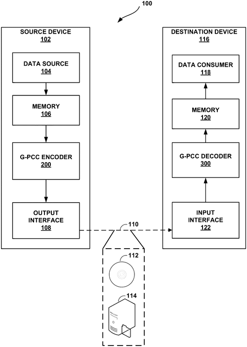
In a recent patent filed by QUALCOMM Incorporated, a new technology known as the G-PCC coder has been described. This coder is designed to receive point cloud data and code it using a final quantization parameter (QP) value, resulting in a coded point cloud. But what does this mean for the average consumer? Point cloud data refers to a collection of points that represent the surfaces of objects in a three-dimensional space, often used in applications such as virtual reality, gaming, and computer-aided design. The G-PCC coder aims to improve the quantization of this data, essentially enhancing its quality and potentially leading to more realistic and detailed virtual environments. While QUALCOMM's patent shows promise, it's important to note that patents alone do not guarantee the development and commercialization of a product. Competition in this field is fierce, with companies like Microsoft and Intel already working on their own solutions for coding point cloud data. Nonetheless, if the G-PCC technology is successfully developed into a product, it could have various uses across industries. For instance, think of the possibilities in entertainment, where filmmakers and game developers could bring even more immersive experiences to their audiences. Additionally, it could aid in the advancement of autonomous vehicles by enhancing their perception systems and improving their ability to interpret the surrounding environment. However, an important question to consider is how accessible this technology will be. Will it remain exclusive to high-end industries and limited to certain applications, or will it eventually find its way into everyday consumer devices? It remains to be seen whether QUALCOMM or its competitors will be able to bring this technology to the masses. What do you think? Would you like to see the implementation of enhanced point cloud coding in your daily life? How do you envision its potential uses? Share your thoughts and opinions in the comments below.
Abstract
A G-PCC coder is configured to receive the point cloud data, determine a final quantization parameter (QP) value for the point cloud data as a function of a node QP offset multiplied by a geometry QP multiplier, and code the point cloud data using the final QP value to create an coded point cloud. A G-PCC coder is configured to receive the point cloud data, determine a final quantization parameter (QP) value for the point cloud data as a function of a node QP offset multiplied by a geometry QP multiplier, and code the point cloud data using the final QP value to create an coded point cloud.
US Patent 11869220
QUALCOMM Incorporated
"Qualcomm's Innovative Patent Allows for Selective Sound Retention and Removal in Audio Signals"
What is this invention?
Audio processing using sound source representations
In a world of sound-rich display,
A device comes out to play,
With processors adept,
Sounds they can intercept,
To enhance or remove, they say.
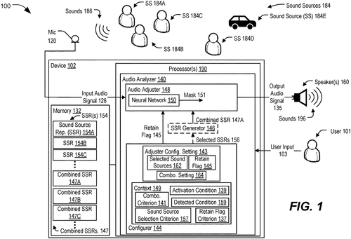
Qualcomm Incorporated recently filed a fascinating patent that could revolutionize the way we experience audio. The patent describes a device that uses advanced processors to process an input audio signal based on a combined representation of multiple sound sources, ultimately generating an output audio signal. But what sets this invention apart is its ability to selectively retain or remove sounds from different sources within the input signal. Imagine a scenario where you're in a crowded café, trying to have a conversation with a friend. With Qualcomm's patent, you could potentially use this device to filter out the background noise and focus solely on your conversation, improving the overall audio experience. This technology could also have exciting applications in broadcasting, allowing broadcasters to enhance audio clarity by removing unwanted background sounds during live events. While the concept behind the patent is undoubtedly exciting, it's important to note that patents don't always translate into marketable products. Currently, we don't have any information on whether Qualcomm intends to bring this invention to market. However, the concept itself opens up a world of possibilities for audio enhancement and personalization. Competitors like Bose and Sony have made significant strides in noise-canceling technologies, with products like the Bose QuietCo. mfort and the Sony WH-1000XM4 garnering praise from consumers. It remains to be seen how this new invention from Qualcomm would fare against the established players in the market. So, what do you think about Qualcomm's audio processing patent? Can you imagine any potential uses for this technology in your everyday life? Let us know your thoughts in the comments below.
Abstract
A device includes one or more processors configured to receive an input audio signal. The one or more processors are also configured to process the input audio signal based on a combined representation of multiple sound sources to generate an output audio signal. The combined representation is used to selectively retain or remove sounds of the multiple sound sources from the input audio signal. The one or more processors are further configured to provide the output audio signal to a second device. A device includes one or more processors configured to receive an input audio signal. The one or more processors are also configured to process the input audio signal based on a combined representation of multiple sound sources to generate an output audio signal. The combined representation is used to selectively retain or remove sounds of the multiple sound sources from the input audio signal. The one or more processors are further configured to provide the output audio signal to a second device.
US Patent 11869478
QUALCOMM Incorporated
"QUALCOMM Incorporated Introduces Innovative Apparatus for Precise Gain Stabilization"
What is this invention?
Gain stabilization
In the realm of technological elevation,
An apparatus brings gain stabilization,
With an amplifier, strong and true,
And a circuit for stabilization too,
Adjusting signals to avoid replication.
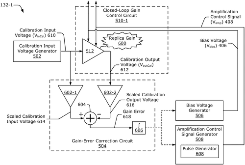
In a recent patent application by QUALCOMM Incorporated, an innovative apparatus for gain stabilization has been described. This apparatus consists of an amplifier and a gain-stabilization circuit, which work together to ensure the stability of the amplifier's gain. The amplifier's gain is determined by a bias voltage and an amplification control signal, both of which play crucial roles in maintaining optimal performance. The gain-stabilization circuit, connected to the amplifier, includes a replica amplifier with a replica gain also influenced by the bias voltage and amplification control signal. The primary function of the gain-stabilization circuit is to adjust either the bias voltage or amplification control signal based on any gain error detected in the replica amplifier. While this patent application showcases a potential breakthrough in gain stabilization technology, it is important to note that successful patent filings do not always result in the creation of marketable products. Competition in this domain is fierce, with existing products from companies like Analog Devices and Texas Instruments already delivering gain stabilization solutions. Therefore, it remains to be seen whether QUALCOMM will commercially develop and release this innovation. The potential applications for such a gain-stabilization apparatus are vast. It could significantly enhance the performance of various electronic devices, ranging from smartphones and laptops to audio equipment and medical devices. By ensuring stable gain, this technology could improve signal quality, reduce distortion, and enhance overall user experience. In conclusion, QUALCOMM's patent application presents an intriguing proposition for gain stabilization. However, the true impact of this innovation will depend on its further development and potential commercialization. How do you think this patent could revolutionize gain stabilization? Share your thoughts in the comments below.
Abstract
An apparatus is disclosed for gain stabilization. In an example aspect, the apparatus includes an amplifier and a gain-stabilization circuit. The amplifier has a gain that is based on a bias voltage and an amplification control signal. The gain-stabilization circuit is coupled to the amplifier and includes a replica amplifier. The replica amplifier has a replica gain that is based on the bias voltage and the amplification control signal. The gain-stabilization circuit is configured to adjust at least one of the bias voltage or the amplification control signal based on a gain error associated with the replica amplifier. An apparatus is disclosed for gain stabilization. In an example aspect, the apparatus includes an amplifier and a gain-stabilization circuit. The amplifier has a gain that is based on a bias voltage and an amplification control signal. The gain-stabilization circuit is coupled to the amplifier and includes a replica amplifier. The replica amplifier has a replica gain that is based on the bias voltage and the amplification control signal. The gain-stabilization circuit is configured to adjust at least one of the bias voltage or the amplification control signal based on a gain error associated with the replica amplifier.
US Patent 11870404
Samsung Electronics Co., Ltd.
"Samsung Patents Dual Blade Robot Lawnmower for Enhanced Grass Cutting Efficiency"
What is this invention?
Robot lawnmower
In the yard, a robot appears,
With blades that it confidently steers,
It mows the lawn with precision,
Driven by a motor's provision,
Grass vanishes, transforming it to cheers!
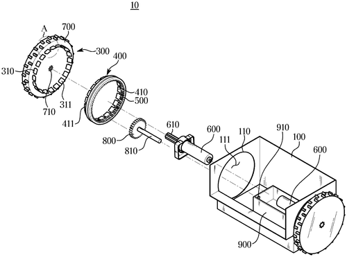
Samsung Electronics has recently filed a patent for a robot lawnmower that aims to bring automation to the tedious task of maintaining a perfectly manicured lawn. The patented design includes a body frame, main wheels on either side, and a motor to drive those wheels. But what makes this robot lawnmower stand out is its innovative blade system. The Samsung robot lawnmower is equipped with two edge blades. The first blade is located in a specific area of the body frame, directly corresponding to the main wheel. This blade can rotate independently, thanks to the driving force provided by the motor. The second edge blade, on the other hand, is positioned between the body frame and the main wheel. It rotates along with the wheel, allowing for a precise and efficient manner of cutting grass through the relative rotation of the two blades. If brought to life, this robot lawnmower could potentially revolutionize the way homeowners maintain their lawns. Imagine a scenario where you can sit back and relax while your lawn is trimmed effortlessly by this autonomous machine. No more sweating in the scorching sun or wasting precious leisure time. Additionally, this inventive design has the potential to achieve an unparalleled level of accuracy, ensuring that every blade of grass is neatly trimmed. However, it is important to note that filing a patent does not necessarily guarantee the production or release of a commercial product. Many patents are simply ideas or concepts that may never see the light of day. In the case of Samsung's robot lawnmower, there are already competing products on the market that offer similar autonomous mowing capabilities. The question remains: Will Samsung bring this patent to life and produce a robot lawnmower that can truly compete with existing options? What are your thoughts on this innovative patent? Do you believe robot lawnmowers will become commonplace in households, or do you find the concept impractical? Let us know in the comments below.
Abstract
Disclosed is a robot lawnmower including a body frame, a main wheel disposed on both sides of the body frame, a motor to drive the main wheel, a first edge blade provided in a region of the body frame corresponding to the main wheel and coupled to be rotatable with respect to the body frame by receiving a driving force of the motor, and a second edge blade disposed between the body frame and the main wheel to rotate together with the main wheel and cut a grass by a relative rotation of the first edge blade and the main wheel. Disclosed is a robot lawnmower including a body frame, a main wheel disposed on both sides of the body frame, a motor to drive the main wheel, a first edge blade provided in a region of the body frame corresponding to the main wheel and coupled to be rotatable with respect to the body frame by receiving a driving force of the motor, and a second edge blade disposed between the body frame and the main wheel to rotate together with the main wheel and cut a grass by a relative rotation of the first edge blade and the main wheel.
US Patent 11864495
Samsung Electronics Co., Ltd.
"Samsung Patents Innovative Cleaning Device with Self-Cleaning Docking Station"
What is this invention?
Cleaning device having vacuum cleaner and docking station and method of controlling the same
There once was a cleaning device,
With technology quite precise.
A vacuum so smart,
Made to clean every part,
With processors controlling the price.
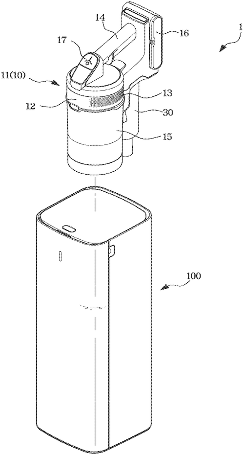
In a recent patent application, Samsung Electronics has introduced a cleaning device that promises to revolutionize the vacuum cleaner industry. The patent describes a vacuum cleaner with a unique docking station that enhances its cleaning capabilities. The cleaning device comprises a vacuum cleaner with a dust collecting container and a docking station to which the container attaches. What sets this device apart is the docking station's suction device, which draws air from the dust collecting container into the station. As the air is moved, a collector within the docking station collects any foreign substances that come along with it. To further enhance its efficiency, the docking station features a suction flow path, controlled by a flow adjusting device, that allows air to circulate within the station. This feature enables the device to periodically open and close the suction flow path based on the operation of the vacuum cleaner. While the patent provides an exciting glimpse into the future of cleaning technology, it is important to note that not all patents make it to the production stage. Even if this device were to come to market, it would likely face competition from established vacuum cleaner manufacturers who have already developed their own innovative products. However, if this patent were to become a reality, it could bring about significant improvements in the cleaning process. Imagine having a vacuum cleaner that not only efficiently collects dust but also automatically cleans its own parts within the docking station. This could greatly simplify maintenance for users while keeping the device performing at its best. As always, we'd love to hear what you think about this patent. Do you think a self-cleaning vacuum cleaner is something you would consider buying? Let us know in the comments below!
Abstract
A cleaning device and a method therefor are provided. The cleaning device includes a vacuum cleaner including a dust collecting container and a docking station to which the dust collecting container is coupled. The docking station includes a suction device configured to move air from the dust collecting container to inside of the docking station, a collector configured to collect a foreign substance that is moved together with the air by driving of the suction device, a suction flow path along which air moves inside the docking station, a flow adjusting device configured to open or close the suction flow path, and at least one processor configured to control the suction device to operate based on the dust collecting container being coupled to the docking station, and control the flow adjusting device to periodically open and close the suction flow path in a state in which the suction device operates. A cleaning device and a method therefor are provided. The cleaning device includes a vacuum cleaner including a dust collecting container and a docking station to which the dust collecting container is coupled. The docking station includes a suction device configured to move air from the dust collecting container to inside of the docking station, a collector configured to collect a foreign substance that is moved together with the air by driving of the suction device, a suction flow path along which air moves inside the docking station, a flow adjusting device configured to open or close the suction flow path, and at least one processor configured to control the suction device to operate based on the dust collecting container being coupled to the docking station, and control the flow adjusting device to periodically open and close the suction flow path in a state in which the suction device operates.
US Patent 11864718
Samsung Electronics Co., Ltd.
"Samsung Develops Innovative Assisting Torque System Based on User's Gait Data"
What is this invention?
Assisting torque setting method and apparatus
In the world of technology advanced,
An assisting torque apparatus, enhanced,
Calculating values with grace,
Setting torques at a steady pace,
Walking with assistance, perfectly entranced.
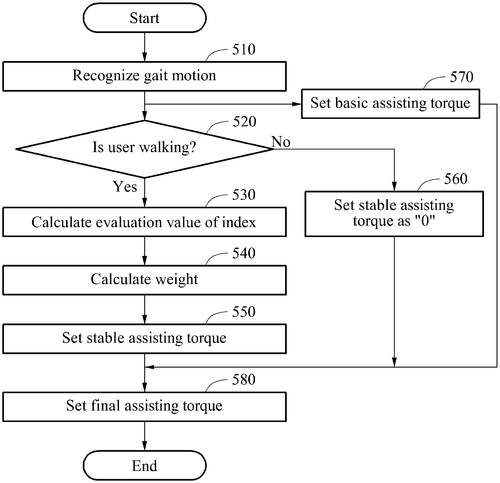
Samsung Electronics Co., Ltd. has recently been granted a patent for an innovative torque setting apparatus and method. This new invention aims to assist users in achieving a stable and personalized torque setting based on their gait data. The assisting torque setting apparatus works by calculating an evaluation value of at least one index using the user's gait data. It then sets a stable assisting torque based on this evaluation value. Additionally, it sets a basic assisting torque that corresponds to the user's specific gait motion, also determined from the gait data. Finally, the apparatus combines the stable assisting torque with the basic assisting torque to generate a final assisting torque. At first glance, this patent from Samsung seems promising, as it addresses the issue of personalized torque settings for users. It acknowledges that each individual has a unique gait, and by analyzing this data, it aims to offer an enhanced user experience. However, it is important to remember that patents do not always translate into actual products or features. In the market, we already have competitors offering similar products for gait analysis and torque settings. Companies such as Fitbit and Garmin have already incorporated gait analysis into their fitness trackers and smartwatches. These devices are designed to provide users with insights into their walking and running patterns. It remains to be seen how Samsung's approach differs from these existing offerings and whether it can truly deliver on its promise. Considering potential uses, this patent could have significant implications for individuals with mobility issues or those in sports and fitness. The ability to accurately tailor torque settings based on gait data has the potential to enhance performance, reduce injury risks, and improve overall user comfort. While it's exciting to see companies like Samsung exploring such innovative concepts, it remains uncertain whether this particular patent will result in a marketable product. The real question is whether Samsung will leverage this patent to develop a tangible product that can truly revolutionize torque settings and bring a new level of personalization to users. What are your thoughts on Samsung's assisting torque setting apparatus? Do you believe it has the potential to make a meaningful impact in the market? Share your opinions and insights in the comments below.
Abstract
Provided is an assisting torque setting apparatus and method, wherein the apparatus is configured to calculate an evaluation value of at least one index based on gait data of a user, set a stable assisting torque based on the evaluation value, set a basic assisting torque corresponding to a gait motion of the user based on the gait data, and set a final assisting torque based on the stable assisting torque and the basic assisting torque. Provided is an assisting torque setting apparatus and method, wherein the apparatus is configured to calculate an evaluation value of at least one index based on gait data of a user, set a stable assisting torque based on the evaluation value, set a basic assisting torque corresponding to a gait motion of the user based on the gait data, and set a final assisting torque based on the stable assisting torque and the basic assisting torque.
US Patent 11865709
Samsung Electronics Co., Ltd.
"Samsung Patents Groundbreaking Robotic Limb with Dual-Reduction Quasi-Direct-Drive Joint Actuators"
What is this invention?
Robotic limb
There once was a limb, quite robotic,
Made of segments, oh so exotic.
With joints and actuators, so fine,
It moved with a fluid design,
Completing tasks with fingers, hypnotic.
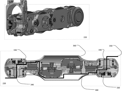
Samsung Electronics Co., Ltd. has recently filed a patent for a fascinating apparatus that could potentially revolutionize the world of robotics. This invention introduces an apparatus for a robotic limb, consisting of multiple limb segments connected via joints. At the heart of this robotic limb are the dual-reduction quasi-quasi-direct-drive joint actuators, which allow for seamless and precise movement throughout a scene. These actuators operate efficiently, paving the way for a more dynamic and agile robotic limb. One of the standout features of this apparatus is its end-effector, which is connected to the free end of the robotic limb. Equipped with one or more opposable fingers comprising a four-bar linkage, the end-effector boasts impressive dexterity. This, coupled with a main actuator, enables the robotic limb to perform a wide range of tasks with precision and finesse. While the concept behind this patent is undeniably exciting, it is crucial to note that the mere existence of a patent does not guarantee that this invention will materialize into a consumer product anytime soon. The technology landscape is fiercely competitive, with industry giants like Boston Dynamics already boasting advanced robotic solutions. Nevertheless, one can envision numerous potential uses for such a robotic limb. From assisting in complex surgeries to aiding in the assembly of delicate machinery, the possibilities seem endless. The ability to seamlessly maneuver and manipulate objects with precision could greatly enhance productivity and efficiency across various industries. It remains to be seen whether Samsung Electronics will successfully bring this apparatus to market. Nonetheless, the patent filing serves as a testament to the ongoing advancements in robotics technology. What potential applications can you envision for this robotic limb? Share your thoughts in the comments below.
Abstract
An apparatus for a robotic limb includes one or more limb segments connected via one or more joints. The robotic limb may feature one or more dual-reduction quasi-quasi-direct-drive joint actuators that permit the robotic limb to move throughout a scene. The robotic limb may further include an end-effector connected to a free end of the robotic limb with one or more opposable fingers comprising a four bar linkage. The end-effector may include a main actuator that actuates the one or more fingers via the four-bar linkages to complete various tasks. An apparatus for a robotic limb includes one or more limb segments connected via one or more joints. The robotic limb may feature one or more dual-reduction quasi-quasi-direct-drive joint actuators that permit the robotic limb to move throughout a scene. The robotic limb may further include an end-effector connected to a free end of the robotic limb with one or more opposable fingers comprising a four bar linkage. The end-effector may include a main actuator that actuates the one or more fingers via the four-bar linkages to complete various tasks.
US Patent 11865714
Samsung Electronics Co., Ltd.
"Samsung Patents Innovative LED Module with Advanced Diffusing Technology"
What is this invention?
Light emitting device modules
In a module of LED great,
An indicator did await,
With diffusing grooves,
To embrace light that moves,
And fill the interior with radiance straight.
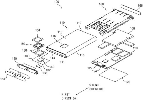
Samsung Electronics has recently filed a patent for an innovative LED module that could potentially revolutionize the lighting industry. The patent describes the inclusion of at least one LED and an indicator within the module. What sets this invention apart is the incorporation of one or more diffusing surfaces, which form an angular diffusing groove. This groove is designed to receive the LED, allowing it to be partially located within a volume space defined by the diffusing surfaces. The purpose of this unique design is to effectively diffuse the light emitted from the LED, diverting it towards the interior of the indicator. By doing so, Samsung aims to create a more evenly diffused lighting effect, resulting in a softer and more pleasant illumination. Although the patent provides an intriguing concept, it is important to note that not all patented technologies find their way into consumer products. Companies like Samsung file numerous patents every year, focusing on innovation and potential future developments. It remains to be seen whether this particular LED module will be translated into a tangible product. That said, the potential applications of this LED module are vast. It could enhance the lighting in various environments, such as homes, offices, and public spaces, creating a more comfortable and visually appealing atmosphere. Additionally, the diffusing technology could be utilized in devices such as smartphones or tablets, where softer and more diffuse lighting can reduce eye strain. Competitors in the lighting industry, such as Philips and Osram, should take note of Samsung's patent. If this invention sees the light of day, it could bring a new level of innovation and competition to the market. In conclusion, Samsung's patent for the LED module with a unique diffusing groove showcases the company's drive for innovation. While it is yet to be determined whether this invention will become a reality, its potential impact on the lighting industry is significant. What do you think? Could this technology revolutionize the way we experience lighting? Share your thoughts in the comments below.
Abstract
An LED module may include at least one LED and an indicator. The indicator may include one or more diffusing surfaces defining an angular diffusing groove. The diffusing groove may receive the LED such that the LED is at least partially located within a volume space defined by the one or more diffusing surfaces. The diffusing groove may diffuse a light emitted from the LED and incident on the one or more diffusing surface of the diffusing groove such that the light is diffused into an interior of the indicator. An LED module may include at least one LED and an indicator. The indicator may include one or more diffusing surfaces defining an angular diffusing groove. The diffusing groove may receive the LED such that the LED is at least partially located within a volume space defined by the one or more diffusing surfaces. The diffusing groove may diffuse a light emitted from the LED and incident on the one or more diffusing surface of the diffusing groove such that the light is diffused into an interior of the indicator.
US Patent 11867366
Micron Technology, Inc.
"New Patent from Micron Technology, Inc. Revolutionizes Oscilloscope Operation"
What is this invention?
Methods for triggering oscilloscopes and oscilloscopes employing the same
In the world of oscilloscopes new,
A method was discovered, it's true.
With pseudo-random bits,
Signal degradation permits,
Eye patterns trigger, a breakthrough!
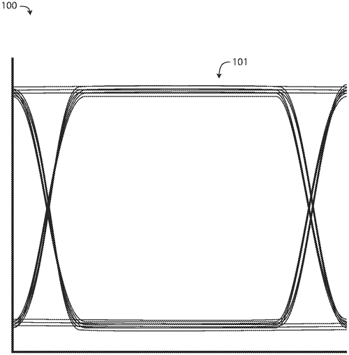
Micron Technology, Inc. has recently filed a patent for a method of operating an oscilloscope that aims to overcome signal degradation issues when triggering a sweep of an eye pattern. This invention could potentially revolutionize the functionality of oscilloscopes and their ability to accurately analyze data. The method involves providing a bit stream containing pseudo-random data to the oscilloscope through a data path that suffers from signal degradation. This degradation would normally hinder the oscilloscope from reliably triggering a sweep of an eye pattern. However, the patent proposes inserting a predetermined sequence of bits into the bit stream at specific intervals, which effectively opens the eye pattern during each interval. This allows the oscilloscope to successfully trigger the sweep of the eye pattern. By generating the eye pattern based on the pseudo-random data while excluding the predetermined sequence of bits from the sweep, the patent ensures accurate analysis without any interference. While this patent presents an intriguing solution to a common problem faced by oscilloscopes, it remains uncertain whether this method will become a practical product in the near future. Competitor's products already exist in the market, providing similar analysis capabilities, albeit with different strategies. If this method were to make its way into commercial production, it could have potential applications in various industries. Oscilloscopes are commonly used in electronics, telecommunications, and scientific research. Further development of this invention could enhance the accuracy and reliability of data analysis in these fields. The question remains, though – will Micron Technology, Inc. pursue the production of this patented method? And if they do, will it truly revolutionize the oscilloscope market? Time will tell. In the meantime, we'd like to hear your thoughts. How do you envision this innovation benefiting the industry? Share your insights in the comments below.
Abstract
A method of operating an oscilloscope is disclosed. The method comprises providing a bit stream comprising pseudo-random data to an oscilloscope across a data path characterized by sufficient signal degradation to prevent the oscilloscope from reliably triggering a sweep of an eye pattern based on receiving the pseudo-random data; inserting a predetermined sequence of bits into the bit stream at predetermined periodic intervals to open the eye pattern sufficiently during each of the periodic intervals to permit the oscilloscope to trigger the sweep of the eye pattern; and generating the eye pattern based at least in part on the pseudo-random data and excluding the predetermined sequence of bits from the sweep of the eye pattern. Oscilloscopes configured to trigger according to a predetermined system of bits at predetermined intervals are also disclosed. A method of operating an oscilloscope is disclosed. The method comprises providing a bit stream comprising pseudo-random data to an oscilloscope across a data path characterized by sufficient signal degradation to prevent the oscilloscope from reliably triggering a sweep of an eye pattern based on receiving the pseudo-random data; inserting a predetermined sequence of bits into the bit stream at predetermined periodic intervals to open the eye pattern sufficiently during each of the periodic intervals to permit the oscilloscope to trigger the sweep of the eye pattern; and generating the eye pattern based at least in part on the pseudo-random data and excluding the predetermined sequence of bits from the sweep of the eye pattern. Oscilloscopes configured to trigger according to a predetermined system of bits at predetermined intervals are also disclosed.
US Patent 11867726
Micron Technology, Inc.
"Micron Technology Unveils Innovative Configurable Computing System for Enhanced Performance"
What is this invention?
Efficient loop execution for a multi-threaded, self-scheduling reconfigurable computing fabric
In the realm of computing so grand,
A system with networks would stand.
Circuits configurable, clusters arrayed,
Instructions and memories, all carefully laid.
Technology's wonders at our command.
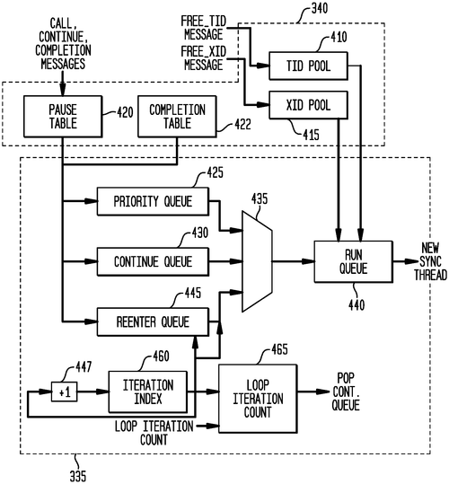
Micron Technology, Inc. has recently unveiled a patent for a groundbreaking technology in the field of configurable computing. This representative apparatus, method, and system brings together various components to create a powerful and versatile computing system. At the heart of this invention lies an interconnection network, acting as the backbone for seamless communication within the system. Alongside this, a processor takes charge, ensuring efficient execution of tasks. The real innovation, however, comes from the inclusion of configurable circuit clusters. These clusters feature an array of configurable circuits, which can adapt and adjust to meet the specific needs of various applications. Each configurable circuit cluster is equipped with both a synchronous network and an asynchronous packet network. This dual network setup allows for efficient data transmission and coordination between the configurable circuits within the cluster. Expanding on the individual components, the configurable circuits themselves boast two noteworthy elements. First, a configuration memory holds a multitude of data path configuration instructions. These instructions serve as the blueprint for configuring the data path of the configurable computation circuit. Second, an instruction and instruction index memory stores a range of spoke instructions and data path configuration instruction indices. These instructions control the selection of key components for the configurable computation circuit, such as the master synchronous input and the current and next data path configuration instructions for subsequent computations. The potential applications for this technology are vast. From various computing tasks to complex data processing and analysis, the ability to reconfigure circuits on-the-fly could greatly enhance versatility and performance. For instance, imagine a data center utilizing this technology to dynamically allocate resources based on changing workloads, leading to greater overall efficiency. While this patent showcases remarkable innovation in the field of configurable computing, it is important to remember that patents do not always translate into commercially available products. Developing and successfully bringing such a complex technology to market would require significant investment and adoption from industry players. This raises an intriguing question: In your opinion, what are some potential hurdles that could prevent the widespread adoption of configurable computing systems? Share your thoughts in the comments below.
Abstract
Representative apparatus, method, and system embodiments are disclosed for configurable computing. A representative system includes an interconnection network; a processor; and a plurality of configurable circuit clusters. Each configurable circuit cluster includes a plurality of configurable circuits arranged in an array; a synchronous network coupled to each configurable circuit of the array; and an asynchronous packet network coupled to each configurable circuit of the array. A representative configurable circuit includes a configurable computation circuit and a configuration memory having a first, instruction memory storing a plurality of data path configuration instructions to configure a data path of the configurable computation circuit; and a second, instruction and instruction index memory storing a plurality of spoke instructions and data path configuration instruction indices for selection of a master synchronous input, a current data path configuration instruction, and a next data path configuration instruction for a next configurable computation circuit. Representative apparatus, method, and system embodiments are disclosed for configurable computing. A representative system includes an interconnection network; a processor; and a plurality of configurable circuit clusters. Each configurable circuit cluster includes a plurality of configurable circuits arranged in an array; a synchronous network coupled to each configurable circuit of the array; and an asynchronous packet network coupled to each configurable circuit of the array. A representative configurable circuit includes a configurable computation circuit and a configuration memory having a first, instruction memory storing a plurality of data path configuration instructions to configure a data path of the configurable computation circuit; and a second, instruction and instruction index memory storing a plurality of spoke instructions and data path configuration instruction indices for selection of a master synchronous input, a current data path configuration instruction, and a next data path configuration instruction for a next configurable computation circuit.
US Patent 11868163
Micron Technology, Inc.
"New Micron Technology Patent Solves Incomplete Programming Error in Memory Cells"
What is this invention?
Granular error reporting on multi-pass programming of non-volatile memory
In a system with memory and might,
A command brought about a fierce fight.
Error arose, oh what a pain,
Flag bits scattered, not in vain.
And unprogrammed pages caused a data flight.

Micron Technology, Inc. has recently patented a system that aims to address data errors in memory cells. This system consists of a memory component that writes flag bits in memory cells after completing a multi-pass programming command. Additionally, there is a processing device connected to the memory component. The primary function of this system is to detect errors while attempting to read the top page of a group of memory cells. It then determines the number of specific values within the flag bits and checks if they meet a predetermined threshold criterion. If the criterion is not satisfied, the system reports an uncorrectable data error to a host computing device. This error is due to incomplete programming of the top page of the memory cell group. While the technicalities of this patent may be complicated, the potential benefits to end-users are clear. By identifying and reporting data errors caused by incomplete programming, this system can help improve the reliability and accuracy of memory storage devices. However, it is important to note that a patent does not guarantee the development of a marketable product. Many ideas, even those protected by patents, never make it to the consumer market. Nevertheless, if Micron Technology can successfully implement this system into their memory products, it could bring about significant advances in data integrity and storage technology. Competitor companies, such as Samsung and Kingston, have been actively working on improving memory technologies to provide faster speeds and higher capacities. In this competitive landscape, the ability to address data errors and ensure reliable storage would certainly give Micron Technology an edge. The potential uses for this system are considerable. It could be applied to various memory devices, including solid-state drives (SSDs), computer RAM, and embedded memory in smartphones and other electronic devices. Ensuring reliable data storage is crucial in fields where accuracy is paramount, such as healthcare, finance, and scientific research. Considering the ever-increasing demand for more reliable and powerful memory solutions, the question arises: Will Micron Technology be able to transform this ambitious patent into a commercially viable product? Let us know your thoughts in the comments below.
Abstract
A system includes a memory component to, upon completion of second pass programming in response to a multi-pass programming command, write a plurality of flag bits within a group of memory cells programmed by the multi-pass programming command. The system also includes a processing device, operatively coupled to the memory component. The processing device is to detect an error in attempting to read a top page of the group of memory cells, determine a number of first values within the plurality of flag bits, and in response to the number of first values not satisfying a threshold criterion, report, to a host computing device, an uncorrectable data error due to the top page of the group of memory cells being incompletely programmed. A system includes a memory component to, upon completion of second pass programming in response to a multi-pass programming command, write a plurality of flag bits within a group of memory cells programmed by the multi-pass programming command. The system also includes a processing device, operatively coupled to the memory component. The processing device is to detect an error in attempting to read a top page of the group of memory cells, determine a number of first values within the plurality of flag bits, and in response to the number of first values not satisfying a threshold criterion, report, to a host computing device, an uncorrectable data error due to the top page of the group of memory cells being incompletely programmed.
US Patent 11868202
Micron Technology, Inc.
"New Patent Reveals Crossed Matrix Parity for Enhanced Memory Device Performance"
What is this invention?
Memory device crossed matrix parity
In a memory device, crossed matrix
Parity protects with great apparatus,
Rows and columns secured,
ECC data ensured,
Repairing or retiring, no status amiss.
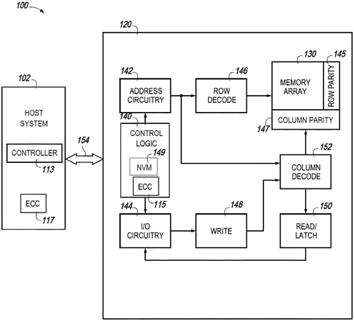
Micron Technology, Inc. has recently patented an intriguing invention that could potentially revolutionize the way memory devices handle data protection. The patent describes methods, devices, and systems that utilize crossed matrix parity to safeguard data stored in memory cells. In simple terms, the concept is to generate two sets of parity data – one set for protecting data stored in rows of memory cells and another set for protecting data stored in columns of memory cells. These sets of parity data are then sent to a host for further error-correcting code (ECC) processing. The host, using the provided sets of parity data, generates ECC data that is then fed back to the memory device. The memory device utilizes this ECC data to repair or potentially retire faulty memory cells, thereby ensuring the integrity of the stored data. While this invention sounds promising, it remains to be seen how it would translate into a tangible product. Memory devices currently available in the market, such as solid-state drives and conventional hard disk drives, employ various forms of ECC to protect stored data. It raises the question of how Micron's crossed matrix parity method would fit into the existing ecosystem and improve upon or surpass existing solutions. Nevertheless, the potential applications of this technology are vast. From consumer electronics like smartphones and laptops to data centers with massive storage arrays, the need for efficient and reliable data protection is paramount. Micron's invention, if successfully implemented, could significantly enhance the reliability and longevity of memory devices, providing peace of mind to users and businesses alike. What are your thoughts on Micron's crossed matrix parity invention? Do you think it will find its way into consumer devices, or will it primarily be utilized in enterprise-level storage solutions? Share your opinions and insights in the comments below.
Abstract
Methods, devices, and systems related to crossed matrix parity in a memory device are described. In an example, a first group of sets of parity data that each protect data stored in a row of memory cells of an array is generated. Further, a second group of sets of parity data that each protect data stored in a column of memory cells of an array is generated. The first set of parity data and the second set of parity data is sent to a host for further ECC processing. The host provides ECC data to the memory device based on the first set of parity data and the second set of parity data. The memory device repairs memory cells or retires memory cells based on the provided ECC data. Methods, devices, and systems related to crossed matrix parity in a memory device are described. In an example, a first group of sets of parity data that each protect data stored in a row of memory cells of an array is generated. Further, a second group of sets of parity data that each protect data stored in a column of memory cells of an array is generated. The first set of parity data and the second set of parity data is sent to a host for further ECC processing. The host provides ECC data to the memory device based on the first set of parity data and the second set of parity data. The memory device repairs memory cells or retires memory cells based on the provided ECC data.
US Patent 11868210
Micron Technology, Inc.
"New Patent by Micron Technology Revolutionizes Memory Error Detection and Correction"
What is this invention?
Error detection and correction in memory
In memory, errors we shall detect,
And correct them with great intellect.
Self-selecting cells,
Marked as erasures, spells,
Perfect data we shall resurrect.
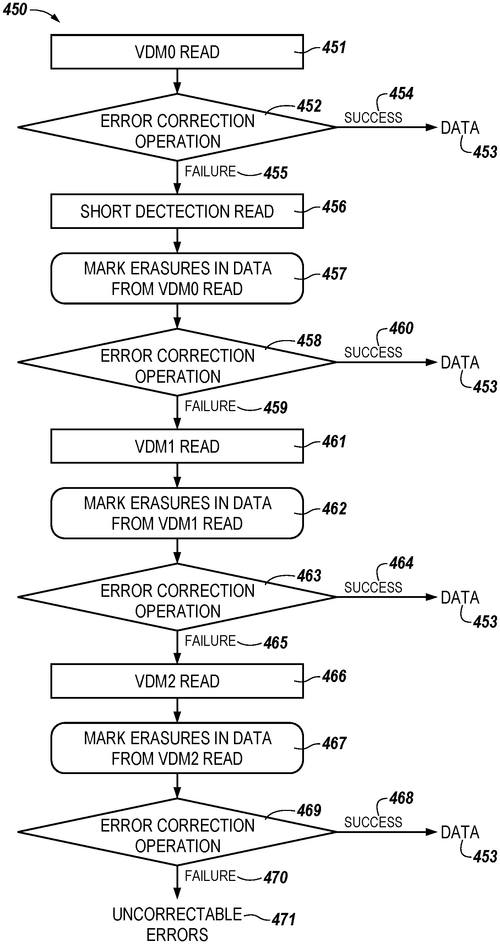
Micron Technology, Inc. has recently filed a patent for an intriguing innovation in error detection and correction in memory. This technology promises to improve the reliability and efficiency of data storage by utilizing self-selecting memory cells and an error correcting code. In simple terms, this patent describes a memory system that can detect and correct errors in stored data. It does so by performing a sense operation on a group of self-selecting memory cells, identifying the cells that cannot store data, marking the data sensed from these cells as erasures, and then performing an error correction operation on the remaining data. While the technical details may be complex, the potential applications of this technology are quite exciting. Imagine a world where memory devices can seamlessly identify and repair errors in real-time, ensuring the integrity and accuracy of stored data. This could revolutionize data storage in numerous industries, from healthcare to finance, where precision and reliability are paramount. That said, it is important to remember that patent filings do not guarantee that a product will be developed or brought to market. Companies like Micron Technology often file patents to protect their intellectual property and explore various avenues of innovation. Therefore, it remains to be seen whether this particular invention will become a reality. In the world of memory technology, there are already existing products that offer error detection and correction capabilities. Competitors like Samsung and SK Hynix have implemented similar features in their memory solutions. The key differentiator for Micron's patent will be the use of self-selecting memory cells and the associated techniques for error correction. In conclusion, Micron Technology's patent showcases a promising advancement in error detection and correction in memory technology. While its potential applications are exciting, only time will tell if this invention will be developed into a viable product. In the meantime, it is worth keeping an eye on Micron Technology's future developments in this field. What do you think about the potential impact of this technology on data storage? How would you envision its application in different industries? Share your thoughts in the comments below.
Abstract
The present disclosure includes apparatuses, methods, and systems for error detection and correction in memory. An embodiment includes a memory having a group of self-selecting memory cells which store data corresponding to a codeword from an error correcting code, and circuitry configured to perform a sense operation on the group of self-selecting memory cells, identify, based on the sense operation, memory cells of the group that cannot store data, mark data sensed from the identified memory cells as erasures and perform an error correction operation on data sensed from the group of self-selecting memory cells with the data sensed from the identified memory cells marked as erasures. The present disclosure includes apparatuses, methods, and systems for error detection and correction in memory. An embodiment includes a memory having a group of self-selecting memory cells which store data corresponding to a codeword from an error correcting code, and circuitry configured to perform a sense operation on the group of self-selecting memory cells, identify, based on the sense operation, memory cells of the group that cannot store data, mark data sensed from the identified memory cells as erasures and perform an error correction operation on data sensed from the group of self-selecting memory cells with the data sensed from the identified memory cells marked as erasures.
US Patent 11868211
SAMSUNG ELECTRONICS CO., LTD.
"Samsung's New Wearable Device Revolutionizes Bio-Signal Measurement through External Light Collection"
What is this invention?
Wearable device and method of measuring bio-signal
There once was a wearable so bright,
With a collector that caught the light.
A sensor did measure,
With auxiliary treasure,
Bio-signals, controlled for the right.
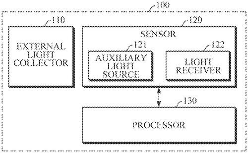
In a recent patent filing, Samsung Electronics Co., Ltd. has revealed an ambitious concept for a wearable device that aims to measure bio-signals through the collection of external light. The device consists of an external light collector, a sensor with an auxiliary light source and a light receiver, and a processor that determines the sufficiency of the external light to measure the bio-signal and controls the auxiliary light source accordingly. While the idea behind this wearable device is certainly intriguing, its practicality and real-world application remain uncertain. The patent does not provide specific details on how the device would actually function or what bio-signals it aims to measure. Similar wearable devices like Fitbit and Apple Watch already exist in the market, offering a range of health monitoring features, including heart rate measurement. It's crucial for Samsung's device to surpass or vastly improve upon the capabilities of these established competitors to gain traction. However, one can imagine potential uses for such a device. It may be utilized in sports and fitness activities, allowing athletes to monitor their bio-signals during training sessions. Additionally, it could have applications in healthcare, enabling medical professionals to remotely monitor patients' vital signs. Nevertheless, as with any patent, there is no guarantee that Samsung's bio-signal measuring wearable will ever materialize as a consumer product. Many patents never see the light of day, remaining confined to the realm of ideas and concepts. It remains to be seen whether Samsung will invest the necessary resources to develop and bring this innovative device to market. What are your thoughts on Samsung's wearable device patent? Do you believe it has the potential to revolutionize the wearable technology industry? Share your opinions and predictions in the comments below.
Abstract
A wearable device includes an external light collector configured to collect external light; a sensor including an auxiliary light source and a light receiver, and configured to measure a bio-signal of an object; and a processor configured to determine whether the external light is sufficient to measure the bio-signal, and to control driving of the auxiliary light source based on the determination. A wearable device includes an external light collector configured to collect external light; a sensor including an auxiliary light source and a light receiver, and configured to measure a bio-signal of an object; and a processor configured to determine whether the external light is sufficient to measure the bio-signal, and to control driving of the auxiliary light source based on the determination.
US Patent 11864871
SAMSUNG ELECTRONICS CO., LTD.
Samsung Introduces Innovative Ink Composition with Nanomaterials and Liquid Vehicles for Enhanced Printing
What is this invention?
Compositions and methods including depositing nanomaterial
Inks of nanomaterial and liquid,
With functional groups that won't solicit,
Cross-linking, they share,
Creating patterns rare,
With inkjet, art's future's explicit.
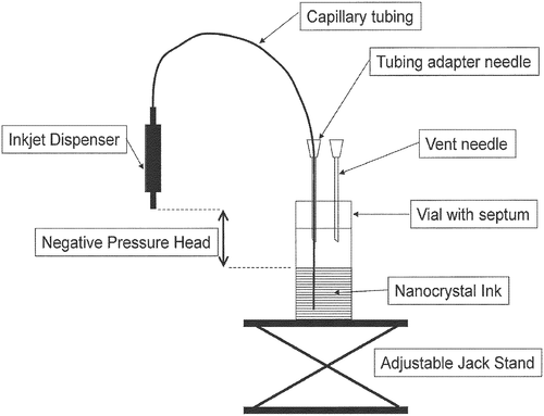
Samsung Electronics Co., Ltd. has filed a patent for an ink composition that could potentially revolutionize the world of inkjet printing. The patent describes an ink that includes a nanomaterial and a liquid vehicle, with various formulations depending on the desired properties. One of the formulations features a liquid vehicle that includes functional groups capable of being cross-linked. This suggests that the ink could potentially offer improved adhesion and durability on different surfaces. Another formulation includes scatterers, which could result in unique visual effects when printed. What is particularly interesting about this patent is the mention of a liquid vehicle with a perfluorocompound. Perfluorocompounds are known for their water and oil repellent properties, which means that this ink could potentially be used for applications requiring water or stain resistance. The patent also highlights the use of semiconductor nanocrystals as the nanomaterial in the ink. These nanocrystals have the potential to add advanced functionalities to the printed materials, such as electronic components or sensors. While this patent showcases a fascinating advancement in ink technology, it is important to note that not all patented inventions make it to market. Many factors come into play, including feasibility, cost, and market demand. However, if this ink composition were to become a reality, it could open up exciting possibilities in various industries. From durable prints for outdoor signage to enhanced security features for documents or even advanced printed electronics, the potential uses are vast. As we eagerly await more news on Samsung's ink composition, we are left wondering: What applications do you envision for this ink? Could it truly revolutionize the world of printing? Share your thoughts in the comments below.
Abstract
An ink composition including a nanomaterial and a liquid vehicle, wherein the liquid vehicle includes a composition including one or more functional groups that are capable of being cross-linked is disclosed. An ink composition including a nanomaterial, a liquid vehicle, and scatterers is also disclosed. An ink composition including a nanomaterial and a liquid vehicle, wherein the liquid vehicle includes a perfluorocompound is further disclosed. A method for inkjet printing an ink including nanomaterial and a liquid vehicle with a surface tension that is not greater than about 25 dyne/cm is disclosed. In certain preferred embodiments, the nanomaterial includes semiconductor nanocrystals. Devices prepared from inks and methods of the invention are also described. An ink composition including a nanomaterial and a liquid vehicle, wherein the liquid vehicle includes a composition including one or more functional groups that are capable of being cross-linked is disclosed. An ink composition including a nanomaterial, a liquid vehicle, and scatterers is also disclosed. An ink composition including a nanomaterial and a liquid vehicle, wherein the liquid vehicle includes a perfluorocompound is further disclosed. A method for inkjet printing an ink including nanomaterial and a liquid vehicle with a surface tension that is not greater than about 25 dyne/cm is disclosed. In certain preferred embodiments, the nanomaterial includes semiconductor nanocrystals. Devices prepared from inks and methods of the invention are also described.
US Patent 11866598
SAMSUNG ELECTRONICS CO., LTD.
"Samsung's New Patent Enhances Screw Tightness in Sheet Metal with Improved Stud Design"
What is this invention?
Stud
In the realm of tech, there's a feat,
A stud with a function quite neat,
It prevents loosening,
With a force intervening,
As torque meets resistance, complete!
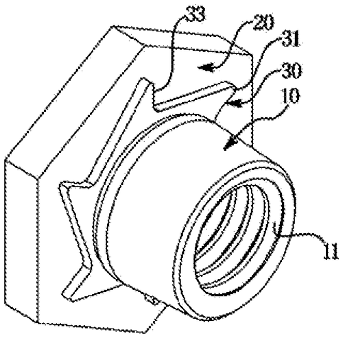
In an effort to address the longstanding issue of loosening studs press-fitted into sheet metal, Samsung Electronics Co., Ltd. has recently filed a patent that proposes a promising solution. This innovation aims to enhance the resistance force against torque, effectively preventing the studs from coming loose over time. Loose studs can be a significant problem in various industries, from automotive to construction, as they can compromise the structural integrity of assembled products. While existing methods have demonstrated some success in preventing loosening, Samsung's patent promises an improved design that tackles the issue head-on. By increasing the resistance force against torque, Samsung's stud patent could potentially eliminate the need for additional measures such as adhesives or lock nuts. This not only simplifies the assembly process but also reduces costs and enhances long-term reliability. However, it's important to note that patents are not guarantees of future products. Companies file patents for numerous inventions, some of which may never see the light of day. Samsung's stud patent exemplifies a commendable attempt to tackle an industry-wide problem, but its feasibility as a consumer product remains uncertain. Moreover, it's worth considering how this potential invention may stack up against existing competition. Are there already established products in the market that effectively address stud loosening? If so, Samsung would need to demonstrate significant advantages or innovations for their patent to stand out. In terms of potential applications, the appliance manufacturing industry could greatly benefit from a robust solution to stud loosening. Additionally, the automotive and construction sectors could also find value in a product that ensures secure and long-lasting structural assemblies. What are your thoughts on Samsung's stud patent? Do you believe the proposed solution has enough potential to become a marketable product, or do you think existing alternatives already fulfill the industry's needs? Share your insights in the comments below.
Abstract
The present disclosure relates to a stud improved to prevent loosening of the stud press-fitted into a sheet metal by increasing a resistance force against a torque. The present disclosure relates to a stud improved to prevent loosening of the stud press-fitted into a sheet metal by increasing a resistance force against a torque.
US Patent 11867221
SAMSUNG ELECTRONICS CO., LTD.
"SAMSUNG Introduces Innovative Cam Assembly in Air Conditioner for Easy Detachable Panel Assembly"
What is this invention?
Air conditioner
In an air conditioner design so neat,
A cam assembly takes the heat.
With contact portions on the cam,
The panel can detach, quite the sham,
As it moves up and down, complete.
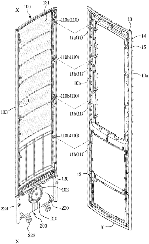
Samsung Electronics has recently filed a patent for an intriguing new feature in air conditioning units. The patent describes an air conditioner with a detachable panel assembly, allowing for easy access and maintenance. The main body of the air conditioner is covered by a panel assembly, which can be removed by a unique cam assembly below. This cam assembly includes a cam with a contact surface that has two different contact portions. These contact portions are designed to interact with the panel assembly at different heights, enabling it to detach from the main body as the cam rotates. While the patent does not provide explicit details about the specific benefits or applications of this design, we can imagine some potential uses. For instance, this detachable panel assembly could allow for more convenient cleaning or repair processes. It might also facilitate easier customization by allowing users to swap out different panels for aesthetic purposes. However, it's important to note that filing a patent does not necessarily mean a product will see the light of day. The patent system is filled with ideas that never materialize into marketable products. Additionally, competitors in the air conditioning industry may already offer similar features or have a different focus for innovation. So, will Samsung implement this detachable panel assembly in their future air conditioner models? Will it become a sought-after feature in the industry? Only time will tell. For now, it remains an intriguing idea waiting to be transformed into a practical solution. What do you think of this patent? Would a detachable panel assembly be valuable to you as an air conditioner user? Share your thoughts in the comments below.
Abstract
Disclosed is an air conditioner including a main body, a panel assembly configured to cover a front surface of the main body and coupled to the main body, and a cam assembly including a cam and disposed below the panel assembly, wherein the cam includes a cam contact surface formed along a rotation direction of the cam, the cam contact surface includes a first contact portion and a second contact portion formed to be in contact with the panel assembly at different heights, and the panel assembly is configured to be detachable from the main body by moving up and down with the rotation of the cam. Disclosed is an air conditioner including a main body, a panel assembly configured to cover a front surface of the main body and coupled to the main body, and a cam assembly including a cam and disposed below the panel assembly, wherein the cam includes a cam contact surface formed along a rotation direction of the cam, the cam contact surface includes a first contact portion and a second contact portion formed to be in contact with the panel assembly at different heights, and the panel assembly is configured to be detachable from the main body by moving up and down with the rotation of the cam.
US Patent 11867425
SAMSUNG ELECTRONICS CO., LTD.
"Samsung's Revolutionary Rotatable Door Design for Refrigerators"
What is this invention?
Refrigerator and home appliance
In the kitchen, a fridge did reside,
With a door that opened wide,
The door body did rotate,
As the panel body's fate,
Was to trim the door with style and pride.
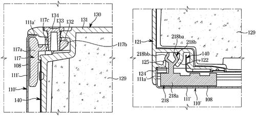
In a recent patent application filed by Samsung Electronics Co., Ltd., a new feature for refrigerators has been revealed. This invention revolves around a door design that includes a rotatable door body, an insulator, and a panel body with two trims positioned at opposite edges. The goal is to enhance the functionality of the refrigerator's storage compartment. While the patent description provides some insight into the potential design of future Samsung refrigerators, it's important to note that not all patented ideas make it into actual consumer products. Many factors, such as market demand, feasibility, and competition, come into play during the development process. Currently, there are already several innovative refrigerators in the market, such as those with touchscreen interfaces, built-in cameras, and advanced cooling technologies. Considering this, it remains to be seen how Samsung's proposed door design will fare against existing products. Will it offer significant advantages over competitors' designs? Can it effectively address common consumer pain points? The potential uses for this new door design are numerous. For example, it could improve insulation, enhance energy efficiency, or potentially even enable customizable panel options to match the kitchen decor. However, it is essential to remember that a patent application does not guarantee the realization of these possibilities. What are your thoughts on this patent application? Do you believe this door design has the potential to revolutionize refrigerators as we know them? Share your insights and opinions in the comments below.
Abstract
A refrigerator including a main body forming a storage compartment, and a door configured to open and close the storage compartment. The door includes a door body rotatably coupled to the main body and including an insulator therein, a panel body positioned in a front of the door body, a first trim disposed at a first edge of the panel body and configured to be coupled to the door body while being rotated with respect to the door body, and a second trim disposed at a second edge opposite to the first edge of the panel body and configured to be coupled to the door body when the first trim is coupled to the door body. A refrigerator including a main body forming a storage compartment, and a door configured to open and close the storage compartment. The door includes a door body rotatably coupled to the main body and including an insulator therein, a panel body positioned in a front of the door body, a first trim disposed at a first edge of the panel body and configured to be coupled to the door body while being rotated with respect to the door body, and a second trim disposed at a second edge opposite to the first edge of the panel body and configured to be coupled to the door body when the first trim is coupled to the door body.
US Patent 11867450
Amazon Technologies, Inc.
"Amazon's New LIDAR System Provides a Game-Changing Field-of-View with Angle Tolerant Birefringent Electro-Optic Shutter"
What is this invention?
Field-of-view compression optics for angle tolerant electro-optic modulators
There once was a LIDAR system so grand,
With a FOV that spanned wide beyond land,
It had a birefringent shutter,
To allow for angles to mutter,
Creating images one could understand.
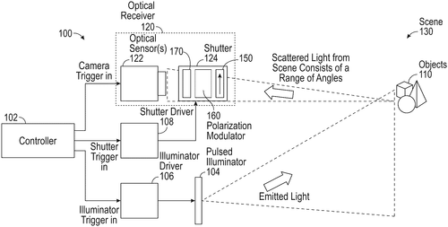
Amazon Technologies, Inc. has recently filed a patent for a novel light detection and ranging (LIDAR) system that promises a large field-of-view (FOV). The system includes an angle-tolerant birefringent electro-optic shutter, an optical system, and one or more image sensors. Let's take a closer look at this intriguing technology. At its core, this LIDAR system utilizes an electro-optic shutter made of birefringent material. The optical system receives optical pulses that bounce back from the surroundings, encompassing a wide range of angles. The magic lies in the optical system's ability to compress these angles into a smaller, more manageable range, below a threshold angle specified by the birefringent material. The electro-optic shutter then captures the modified optical signals, allowing the image sensor(s) to generate a comprehensive and detailed image of the environment. This patent demonstrates Amazon's ambition to enhance its capabilities in the field of LIDAR technology. LIDAR has become a crucial component in various applications, including autonomous vehicles, robotics, and environmental monitoring. Competitors like Waymo, Tesla, and Velodyne are already utilizing LIDAR systems in their own products, making it a highly competitive market. The potential uses for this advanced LIDAR system are vast. Autonomous vehicles could benefit from the wider field-of-view, enabling improved perception and detection of obstacles. Robotics could utilize this technology to enhance object recognition and navigation capabilities, improving their efficiency in complex environments. Furthermore, environmental monitoring agencies could rely on this system to gather precise 3D data about landscapes, forests, and infrastructure. However, it is worth noting that filing a patent does not necessarily guarantee that this technology will be developed into a marketable product. Many patents never see the light of day beyond the filing stage, so it remains to be seen whether Amazon will indeed bring this innovation to life. What do you think about Amazon's latest patented LIDAR system? Can you envision any other potential applications for this technology? Share your thoughts and opinions in the comments below.
Abstract
A light detection and ranging (LIDAR) system that provides a large field-of-view (FOV) includes an angle tolerant birefringent electro-optic shutter, an optical system, and one or more image sensors. The electro-optic shutter includes a birefringent material. The optical system is configured to receive optical pulses that are reflected from an environment and that include a first set of angles. The optical system is configured to compress the first set of angles into a second set of angles below a threshold angle associated with the birefringent material. The electro-optic shutter is configured to receive the optical signals with the second set of angles. The image sensor(s) are configured to generate an image of the environment based on the optical pulses with the second set of angles that pass through the electro-optic shutter. A light detection and ranging (LIDAR) system that provides a large field-of-view (FOV) includes an angle tolerant birefringent electro-optic shutter, an optical system, and one or more image sensors. The electro-optic shutter includes a birefringent material. The optical system is configured to receive optical pulses that are reflected from an environment and that include a first set of angles. The optical system is configured to compress the first set of angles into a second set of angles below a threshold angle associated with the birefringent material. The electro-optic shutter is configured to receive the optical signals with the second set of angles. The image sensor(s) are configured to generate an image of the environment based on the optical pulses with the second set of angles that pass through the electro-optic shutter.
US Patent 11867899
Amazon Technologies, Inc.
"Amazon Patents AI-Powered Reliable Route Planner for Aerial Vehicles"
What is this invention?
Selecting safe flight routes based on localized population densities and ground conditions
In a map of reliability we find,
Data and populations intertwine.
With a grid and uniform cells,
Treading safely, where danger dwells,
Avoiding crowds and structures, designed.
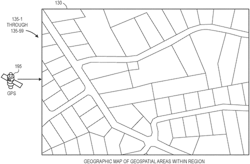
In a patent filed by Amazon Technologies, Inc., a new concept for generating a reliability map has been described. This map combines population data with a geographic map of a region, resulting in a grid of uniform cells. Each cell is then assigned a density value based on the population or other intrinsic data associated with that specific area. This innovative approach aims to assist in the navigation of aerial vehicles by identifying safe routes that avoid high population density or critical infrastructure such as schools, hospitals, or public safety buildings. The potential uses for this reliability map are vast. Imagine a scenario where delivery drones are commonplace, and packages need to be transported efficiently and safely. By utilizing this technology, drones could avoid crowded areas and congested regions, ensuring a smooth and secure delivery process. Additionally, emergency services could benefit from this invention by using it to chart the most reliable and efficient routes for reaching their destinations. While this patent shows promise, it is important to note that not every invention described in patents actually materializes as a consumer product. The technology outlined by Amazon Technologies, Inc. could have far-reaching implications for a variety of industries, but we must wait and see if it will be developed into a practical and marketable solution. In today's world, where both the demand for delivery services and the need for efficient emergency response are higher than ever, this invention carries significant potential. The question remains: Will we see this reliability map become a reality or simply remain an intriguing concept on paper? Share your thoughts in the comments below and let us know if you would find such a technology useful in your daily life or business operations.
Abstract
A reliability map is generated by superimposing or associating populations or other intrinsic data is superimposed or associated with a geographic map of a region, which is divided into a grid having cells of uniform size. Densities of towns, cities or other geospatial areas are determined and assigned to cells of the grid, which have sizes corresponding to minimum dimensions of a corridor required for travel by an aerial vehicle. When a mission requiring travel from an origin to a destination within the region is identified, one or more paths of a safe route between the origin and the destination are selected based on the reliability map. The safe route is selected to avoid areas of high population density or locations of critical infrastructure such as schools, hospitals or public safety buildings. A reliability map is generated by superimposing or associating populations or other intrinsic data is superimposed or associated with a geographic map of a region, which is divided into a grid having cells of uniform size. Densities of towns, cities or other geospatial areas are determined and assigned to cells of the grid, which have sizes corresponding to minimum dimensions of a corridor required for travel by an aerial vehicle. When a mission requiring travel from an origin to a destination within the region is identified, one or more paths of a safe route between the origin and the destination are selected based on the reliability map. The safe route is selected to avoid areas of high population density or locations of critical infrastructure such as schools, hospitals or public safety buildings.
US Patent 11868145
Amazon Technologies, Inc.
"Amazon's New Patent Revolutionizes On-Demand Code Execution with Reduced Memory Footprint"
What is this invention?
On-demand code execution with limited memory footprint
In a coordinated code environment,
On-demand tasks find swift deployment,
With reduced memory load,
Devices share executable code,
Efficient execution, a commendable employment.
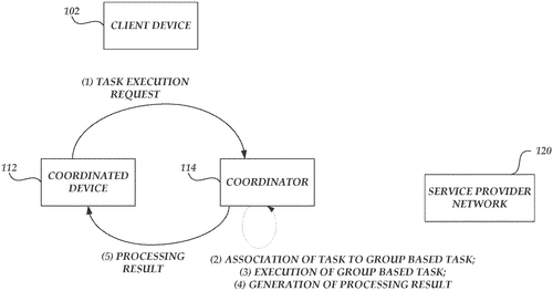
Amazon Technologies, Inc. has recently filed a patent for a new system that aims to streamline the execution of on-demand code while minimizing the required memory footprint. This technology is designed to enable coordinated devices to efficiently carry out code execution requests by associating them with groups that share executable code. The concept behind this system is intriguing, as it offers a potential solution for computing devices with limited resources. By reducing the memory footprint required for executing on-demand tasks, coordinated devices with more modest computing capabilities could still effectively handle these requests without the need for separate loading and execution of the on-demand executable code. While the patent does not provide specific details on how this coordinated environment would function, it opens up possibilities for various applications. For instance, this technology could be used in smart home devices or Internet of Things (IoT) systems to optimize code execution and enable seamless interaction between multiple connected devices. Considering the growing market for smart home solutions, it would be exciting to see how this patent could potentially shape the future of coordinated devices. However, it is important to remember that not all patented technologies make it to the market. Many factors, such as technological feasibility and commercial viability, come into play when determining whether an invention will be turned into an actual product. In the realm of smart home solutions, competitors such as Google's Nest and Apple's HomeKi. t have already established their presence with successful products. Whether Amazon Technologies, Inc. can leverage their patent to deliver a practical and competitive product remains to be seen. What are your thoughts on this patent? Do you believe reducing the memory footprint of code execution in coordinated devices is a game-changer for the smart home industry? Share your opinions in the comments below!
Abstract
Systems and methods are described for management of a coordinated environment for execution of on-demand code with reduced memory footprint provided. A coordinator receives individual on-demand code execution requests or tasks from coordinated devices. The coordinate can process the on-demand code execution requests to associate at least a subset of the on-demand code execution with one or more groups sharing executable code. The coordinated device can implement the execution of the individual tasks without requiring a separate loading and execution of the on-demand executable code. Accordingly, the coordinated device may be implemented on computing devices having more limited computing resources by reducing the memory footprint required to execute the on-demand task. Systems and methods are described for management of a coordinated environment for execution of on-demand code with reduced memory footprint provided. A coordinator receives individual on-demand code execution requests or tasks from coordinated devices. The coordinate can process the on-demand code execution requests to associate at least a subset of the on-demand code execution with one or more groups sharing executable code. The coordinated device can implement the execution of the individual tasks without requiring a separate loading and execution of the on-demand executable code. Accordingly, the coordinated device may be implemented on computing devices having more limited computing resources by reducing the memory footprint required to execute the on-demand task.
US Patent 11868164
Amazon Technologies, Inc.
"Amazon's Innovative Patent Allows for Reliable Power Backup in Datacenters and Devices"
What is this invention?
Battery mitigated datacenter power usage
In data centers, devices take power,
From external sources, hour by hour.
But when costs hike high,
Or power's supply dry,
Backup systems revive, like a flower.
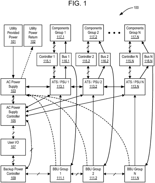
In a recently published patent, Amazon Technologies Inc. has unveiled potential methods for providing power to electronic components, such as servers in data centers or other devices. The patent suggests a solution for situations when the demand for external AC power is high, driving up costs, or when the availability of external AC power is limited. In such scenarios, the patent proposes using distributed backup power supply systems to temporarily offset or even reverse the consumption of external AC power. According to the patent, these distributed backup power systems would be periodically recharged during periods of low power demand, ensuring a consistent and adequate charge for backup use in the event of power loss. This innovative approach could have a significant impact on reducing costs and improving reliability in data centers and other electronic devices. While the concept is intriguing, it is important to remember that patents do not always translate directly into finished products or solutions. It remains to be seen whether Amazon Technologies Inc. will pursue the development and commercialization of this technology. Additionally, it is worth considering how this patent might stack up against existing backup power solutions available in the market today. Competitors such as UPS systems and generators have long been relied upon by data centers and other industries requiring reliable backup power. However, the patent does open up intriguing possibilities for the future. Beyond data centers, distributed backup power supply systems could find applications in various industries, such as telecommunications, healthcare, or even residential settings. The ability to offset or reverse power consumption during peak demand or critical situations could lead to cost savings and improved operational efficiency. The question remains: Will Amazon Technologies Inc. take this concept beyond the patent stage and bring it to market? And if they do, how will this innovation stack up against existing backup power solutions? Now, we turn it over to you, our readers. What do you think of this patent and its potential applications? Do you believe distributed backup power supply systems could revolutionize how we provide power to electronic components? Share your thoughts and insights in the comments below.
Abstract
Methods for providing power to electronic components (e.g., servers in a datacenter, or other devices) can include providing AC power received from an external source to the devices. During periods of high demand, when costs of external AC power exceed a threshold, or when availability of external AC power is decreased, distributed backup power supply systems can be utilized to temporarily offset or to reverse consumption of external AC power. Such distributed backup power systems can be periodically recharged during periods of low power demand, and thus consistently retain adequate charge for backup use in the event of power loss. Methods for providing power to electronic components (e.g., servers in a datacenter, or other devices) can include providing AC power received from an external source to the devices. During periods of high demand, when costs of external AC power exceed a threshold, or when availability of external AC power is decreased, distributed backup power supply systems can be utilized to temporarily offset or to reverse consumption of external AC power. Such distributed backup power systems can be periodically recharged during periods of low power demand, and thus consistently retain adequate charge for backup use in the event of power loss.
US Patent 11868191
****
Introducing the DROVEL™: The Ultimate Multipurpose Drain Tool and Pry Bar
What is this invention?
Multipurpose drain tool
There once was a tool called DROVEL,
For drains it had quite the novel.
With shovel and pry,
It cleared drains so high,
Restoring functionality, it did marvel.

A new patent for a multipurpose drain tool has been making waves in the plumbing world. Dubbed the "DROVEL™," this innovative invention combines a drain shovel and a pry bar into a single handy device. The multipurpose drain tool boasts a drain tool shaft with rubber hand grips at its base and tip, a pry bar that extends outwardly from one end, and a drain shovel that extends distally from the other end. The key selling point of the DROVEL™ is its ability to tackle the recurring issue of clogged subsurface drains, providing a much-needed solution to restore optimal drain functionality. By incorporating both a shovel and a pry bar in one tool, plumbers and DIY enthusiasts alike can now effortlessly clear blockages and debris, improving the overall efficiency and effectiveness of drain clearing operations. While the concept of the multipurpose drain tool is undeniably impressive, its real-world viability remains to be seen. Plumbing professionals often rely on a range of specialized tools when tackling drain-related tasks. There are already established competitors in the market, each with their own specialized equipment, designed to address specific challenges in drain clearing. However, the DROVEL™ does open up the possibility of streamlining the cluttered toolbox of plumbing professionals, potentially making their work more efficient and convenient. Furthermore, DIY enthusiasts seeking a versatile tool for occasional drain maintenance might find value in the multipurpose functionality offered by the DROVEL™. It will be interesting to observe whether this patent will be transformed into a market-ready product. Plumbing companies and manufacturers alike will have to carefully consider the demand, practicality, and cost-effectiveness of the DROVEL™ in comparison to existing offerings. Only time will tell if this invention can carve out a niche in the competitive world of plumbing tools. The question remains, dear readers: Would you consider adding the multipurpose DROVEL™ to your toolkit? Share your thoughts and opinions in the comments below.
Abstract
A multipurpose drain tool including a drain shovel “DROVEL™” and pry bar. The multipurpose drain tool includes a drain tool shaft, a proximal pry bar, and a distal drain shovel. The drain tool shaft carries at least one rubber hand grip, a proximal end cap, and a distal end cap. The pry bar is mounted to and extends outwardly from the proximal end cap. The drain shovel is mounted to and extends distally from the distal end cap. The multipurpose drain tool of the present invention offers a solution to the problem of clearing subsurface drains to restore drain functionality. A multipurpose drain tool including a drain shovel “DROVEL™” and pry bar. The multipurpose drain tool includes a drain tool shaft, a proximal pry bar, and a distal drain shovel. The drain tool shaft carries at least one rubber hand grip, a proximal end cap, and a distal end cap. The pry bar is mounted to and extends outwardly from the proximal end cap. The drain shovel is mounted to and extends distally from the distal end cap. The multipurpose drain tool of the present invention offers a solution to the problem of clearing subsurface drains to restore drain functionality.
US Patent 11864479
****
"Revolutionary Harrow Patent Enhances Soil Tilling Efficiency with Spring Biasing Units"
What is this invention?
Cultivator
There once was a harrow, so smart,
With tines and a spring in each part.
The frame could shift,
With a nifty act of a gift.
Pressing lower arms, it would impart.
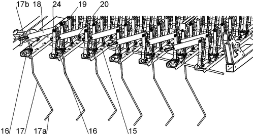
In a recent patent filing, a new invention for a harrow has been described, outlining a number of innovative features aimed at improving its efficiency and effectiveness. The harrow, a widely-used agricultural tool for breaking up and smoothing soil surfaces, features a frame with pivotal tines and lower arms that interact with the soil. What sets this patent apart is the introduction of a novel actuator and spring biasing units that promise to enhance the performance of the harrow. The patent describes an actuator mounted on the frame that can shift a bar frame horizontally. Above the tines, there are spring biasing units that consist of guide elements connected to the bar frame. These guide elements follow a predetermined displacement path, along with connecting elements that are attached to the upper arms of the tines. A first compression spring exerts pressure on both elements, pushing the lower arm of each tine into the soil surface when the guide element moves along its path. Additionally, a second compression spring continuously engages with one of the elements, connecting with the other element after it has moved only partially along its path. While the patent details the inner workings of this innovative harrow, it is important to remember that having a patent does not guarantee that a product will be developed or brought to market. This particular harrow concept faces competition from existing models and brands in the agricultural machinery industry, where efficiency and productivity are already highly valued. Whether this invention will see the light of day as a commercially available product remains to be seen. If this harrow were to become a reality, it has the potential to revolutionize soil preparation in agriculture. The combination of the actuator and spring biasing units could provide farmers with a powerful tool to quickly and effectively break up and level the soil surface, potentially reducing the time and effort required for certain agricultural tasks. However, until further development and testing take place, it is difficult to predict the true impact and practicality of this invention. In conclusion, this patent presents an intriguing concept for a harrow that could disrupt the agricultural machinery market. Its innovative design and promising features certainly warrant attention. Nevertheless, it remains to be seen whether this invention will be transformed into a tangible product that can deliver on its potential. We eagerly await updates on the progress of this harrow and invite you to share your thoughts on whether such a technological breakthrough is necessary or viable in today's agricultural landscape.
Abstract
A harrow has a frame, tines pivotal on the frame and each a lower arm with a soil surface under the harrow. An actuator on the frame can shift a bar frame shiftable horizontally on the frame. Respective spring biasing units above the axes each have a guide element connected to the bar frame and displaceable therewith through a predetermined displacement path, a connecting element connected to respective upper arms of the tines, a first compression spring bearing on both of the elements and biasing the other element away from the one element so as to press the lower arm downward into the soil surface during movement of the respective guide element through the path, and a second compression spring bearing continuously on one of the elements and engageable with the other of the elements after displacement of the respective spring-biasing unit only through a part of the path. A harrow has a frame, tines pivotal on the frame and each a lower arm with a soil surface under the harrow. An actuator on the frame can shift a bar frame shiftable horizontally on the frame. Respective spring biasing units above the axes each have a guide element connected to the bar frame and displaceable therewith through a predetermined displacement path, a connecting element connected to respective upper arms of the tines, a first compression spring bearing on both of the elements and biasing the other element away from the one element so as to press the lower arm downward into the soil surface during movement of the respective guide element through the path, and a second compression spring bearing continuously on one of the elements and engageable with the other of the elements after displacement of the respective spring-biasing unit only through a part of the path.
US Patent 11864481
****
"Cutting-Edge Shearing Mechanism with Continuous Velocity and Precision"
What is this invention?
Shearing mechanism
In the realm of blade and motion,
A shearing mechanism in motion,
Blades overlap with grace,
Velocity won't erase,
Cutting through objects with devotion.
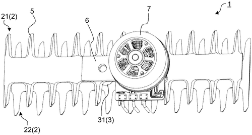
In a recently filed patent, an intriguing shearing mechanism is described that promises to streamline the cutting process. This invention features a pair of blade units, each equipped with shearing blades, and a motion mechanism that enables one of the blade units to move along a predetermined trajectory while maintaining the relative posture of the pair. This innovative design ensures that the moving blade unit maintains a non-zero velocity throughout the cutting process. While the patent description provides a technical explanation of how this shearing mechanism works, it leaves us with some questions about potential applications and practicality. Will this invention find its place in industries like manufacturing, where precise and efficient cutting tools are in high demand? Could it potentially compete with existing cutting-edge devices like laser cutters or water jet machines? Although we are always excited to see new technological innovations, it's important to remember that not all patented ideas end up as successful products. While this shearing mechanism holds promise, it remains to be seen if it can overcome the challenges of implementation and meet the demands of industrial users. In the meantime, we invite you, our readers, to share your thoughts. Do you think this shearing mechanism could revolutionize the cutting industry? What other potential uses do you imagine for this technology? Let us know in the comments below.
Abstract
A shearing mechanism is provided including a pair of blade units comprising shearing blades respectively; and a motion mechanism configured to move at least one of the pair of blade units along a predetermined trajectory in such a manner that a velocity thereof does not become zero while maintaining a relative posture of the pair of blade units, wherein the pair of blade units are configured to cut an object by overlapping the shearing blades of each other during the motion. A shearing mechanism is provided including a pair of blade units comprising shearing blades respectively; and a motion mechanism configured to move at least one of the pair of blade units along a predetermined trajectory in such a manner that a velocity thereof does not become zero while maintaining a relative posture of the pair of blade units, wherein the pair of blade units are configured to cut an object by overlapping the shearing blades of each other during the motion.
US Patent 11864489
****
"Revolutionizing Vine and Cane Pruning: Introducing the Innovative Toothed Wheel Pruning Apparatus"
What is this invention?
Pruning apparatus
In vineyards where growth is profuse,
A new apparatus does diffuse,
With a wheel toothed and keen,
It guides over green,
And cuts through the vines with great use.
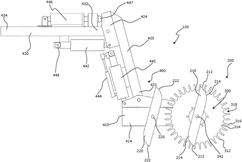
In a patent recently filed by an ambitious inventor, a new vine or cane pruning apparatus has been described. The patent outlines a toothed wheel that acts as a guide for the pruning apparatus, with a multitude of teeth distributed around its circumference. These teeth are designed to catch vegetation, effectively pruning the vines or canes as the apparatus is driven along a row. What sets this invention apart from traditional pruning tools is the inclusion of a driven rotary cutter mounted coaxially with the wheel. The rotary cutter is configured in such a way that its effective cutting area falls within the diameter of the wheel, allowing for precise and efficient trimming of vegetation caught between the teeth. While this patented invention showcases promise for improving efficiency in vine and cane pruning, it is important to remain pragmatic about its potential as a product. As with any patent, there are several factors that can hinder its commercialization, such as feasibility, cost-effectiveness, and competition from existing pruning tools in the market. Competitors in this field have already developed a variety of pruning shears, electric saws, and even robotic systems that aim to streamline the process and reduce labor costs. It remains to be seen whether this new vine or cane pruning apparatus can outperform these established solutions or find its niche in the market. Looking beyond vine and cane pruning, one can envision potential applications for this toothed wheel and rotary cutter technology in other sectors. It might be adapted for use in forestry, agriculture, or even landscaping, for tasks that require cutting and pruning vegetation with precision and speed. As we celebrate innovation, it is crucial to consider the practicality and market viability of new inventions. So, what are your thoughts on this vine or cane pruning apparatus? Could this patent truly revolutionize the pruning industry? Share your views and opinions in the comments below.
Abstract
A vine or cane pruning apparatus, comprising a toothed wheel for guiding the pruning apparatus over vegetation in use, the wheel comprising a multiplicity of generally radially projecting teeth distributed about the periphery of the wheel for catching vegetation between gaps of the teeth, and wherein the wheel rotates by consequence of its engagement with the vegetation and vine or cane posts as the apparatus is driven along a row of vines or canes for pruning; and a driven rotary cutter mounted co-axially to the wheel for cutting vegetation caught between the teeth, the cutter being configured such that its effective cutting area falls within the diameter of the wheel. A vine or cane pruning apparatus, comprising a toothed wheel for guiding the pruning apparatus over vegetation in use, the wheel comprising a multiplicity of generally radially projecting teeth distributed about the periphery of the wheel for catching vegetation between gaps of the teeth, and wherein the wheel rotates by consequence of its engagement with the vegetation and vine or cane posts as the apparatus is driven along a row of vines or canes for pruning; and a driven rotary cutter mounted co-axially to the wheel for cutting vegetation caught between the teeth, the cutter being configured such that its effective cutting area falls within the diameter of the wheel.
US Patent 11864497
****
"Revolutionary Tree Box Patent Allows for Easy Transport and Replanting"
What is this invention?
Tree box
There once was a tree box so grand,
With sidewalls and a removable bottom in hand,
It helped transport trees,
With ease and with ease,
Plastic portions formed, aiding nature's demand.
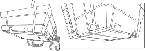
In the world of horticulture, efficiency and convenience are paramount when it comes to growing and transporting trees. A recent patent has caught our attention, describing a tree box that aims to revolutionize these processes. The box features sidewalls and a removable bottom panel, allowing for easy removal before replanting. What's more, portions of the tree box are made of a plastic material, potentially enhancing durability and reducing weight. This new invention brings a fresh take on a traditional practice, offering benefits that could attract gardeners and landscapers alike. The ability to remove the bottom panel simplifies the replanting process, saving valuable time and effort. Additionally, the incorporation of plastic materials could potentially make the tree box more robust, ensuring the safe transport of trees to their final destinations. While this patent presents an intriguing concept, as with any innovation, its transformation into a tangible product is uncertain. The horticultural market is not devoid of existing tree-growing and transporting solutions. Competing products, such as fabric root bags or wooden crates, have already established their positions in the industry. Nevertheless, there are potential applications for this new tree box design. It could streamline the tree transplanting process in urban landscapes where green spaces are limited, enabling the efficient transport and replanting of larger trees. Moreover, the plastic material used in certain embodiments might offer advantages over conventional materials in terms of durability and cost-effectiveness. As we eagerly anticipate further developments, our question to you, our readers, is: Would you opt for a tree box equipped with removable panels, or do you find the current alternatives satisfactory? Share your thoughts in the comments below!
Abstract
A tree box for growing and transporting a tree includes sidewalls and a removable bottom panel. The bottom panel can be removed prior to replanting the tree. In some embodiments portions of the tree box are formed of a plastic material. A tree box for growing and transporting a tree includes sidewalls and a removable bottom panel. The bottom panel can be removed prior to replanting the tree. In some embodiments portions of the tree box are formed of a plastic material.
US Patent 11864501