Most innovative companies for 11/21/2023 (new inventions)
Exciting new inventions from International Business Machines Corporation, Apple Inc., Canon Kabushiki Kaisha, Dell Products L. P. And Microsoft Technology Licensing, Llc
This is a weekly article summarizing a handful of inventions from the most innovative companies in the world. The summaries are created by an A. I. and proof-read by a human before publication. Attempts are made to ensure accuracy of the descriptions, but it is very much a work in progress. Each invention description is preceeded by a poem about the invention that is written by the A. I. I have found the limerick is actually quite good at explaining the invention in simple terms. Enjoy!
****
See the thickness of your object before you buy it!
What is this invention?
Devices, systems and methods for evaluating objects subject to repair or other alteration
A method for inspecting an object was sought
And with it, a way to identify and measure the thickness of a layer at points they thought;
So augmented reality device they used,
To view the object and detect regions of interest that were fused;
The images and measurements sent to the server system,
Adjusting value based on what's seen - no one can deny this wisdom!
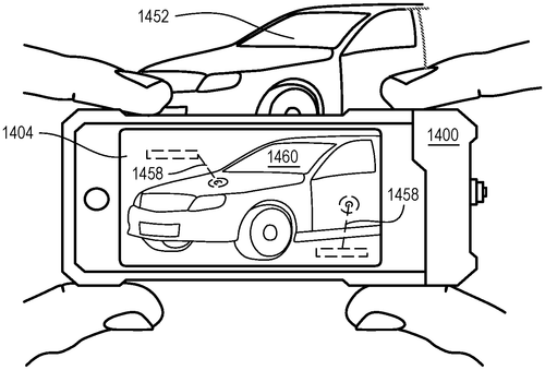
In a recent patent filing, a company has proposed a method that combines augmented reality technology with inspection devices to measure the thickness of layers on objects. While this invention sounds promising, it's important to consider whether it will actually make it to the market. The patent describes a method where an inspection device identifies an object and an augmented reality device is used to view the object and identify specific points for inspection. The thickness of layers at these inspection points can then be measured. If a region of interest is detected on the surface of the object, an image of that region can be taken. All the data, including the measurements and images, can be transmitted to a server system to adjust the value of the inspected object. On the surface, this technology has potential applications in various industries. For example, in manufacturing, it could be used to quickly and accurately measure the thickness of coatings or layers on products. In construction, it could aid in inspecting the quality of materials used. The possibilities are intriguing. However, it's important to note that this is still just a patent filing and not an actual product. Many factors can prevent an invention from becoming a reality, such as technical challenges, market demand, or competing products offering similar functionality. Additionally, the patent description lacks specific details on how the augmented reality and inspection devices would work together seamlessly, which raises doubts about its feasibility. While it's exciting to see innovative ideas like this being explored, it remains to be seen whether this particular invention will make its way into our everyday lives. Only time will tell if it can overcome the hurdles and become a practical solution. What are your thoughts on this proposed method? Can you envision any other potential uses for this technology? Leave your comments below.
The text describes a method for inspecting an object, which can include identifying the inspected object with an inspection device, viewing the inspected object through an augmented reality device to identify points, and measuring a thickness of a layer at the inspection points. In response to detecting a region of interest on the surface of the inspected object, an image of the region of interest can be taken. By operation of communication circuits, at least the thickness measurements and images can be transmitted to a server system. The value of the inspected object can be adjusted based on at least the thickness measurements and images from the at least one inspection device.
US Patent 11821728
****
Get Ahead of the Crowd with Dynamic Promotions
What is this invention?
Dynamic promotions based on vehicle positioning and route determinations
A system of route optimization,
Provides dynamic promotions with precision.
For a better quality score,
The customer may go to an alternate core,
And be rewarded for their decision.
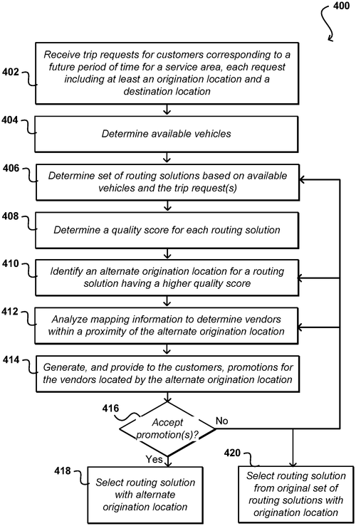
In a recently published patent, a new technique for route optimization is described, aimed at improving the overall experience of ride-hailing services. The system employs dynamic promotions that are synchronized with the predicted time of arrival of a vehicle, in response to a ride request. These promotions are designed to compensate for wait times or unexpected delays, benefiting both customers and vendors. One innovative feature of this route optimization system is its ability to incentivize customers to go to an alternate pickup location that offers a more optimized route for the assigned vehicle. By calculating a quality route score and comparing it to the original pickup location, the system can determine if there is a better option available. In such cases, dynamic promotions would be provided to encourage customers to choose the alternate pickup location, reducing inefficiencies and wait times. At first glance, this patent appears to address a common frustration among riders and drivers alike - the time spent waiting for a ride. By compensating for delays and offering more optimized routes, it has the potential to enhance the overall efficiency of ride-hailing services. However, as with any patent, the question remains whether this innovation will ever see the light of day as a tangible product. The market for ride-hailing services is highly competitive, with companies constantly striving to outdo one another in terms of features and performance. Established players like Uber and Lyft already offer their own route optimization algorithms, and it remains to be seen if this patent will be implemented or if similar features will be developed independently. Furthermore, execution and integration with existing platforms could pose challenges. While the idea of dynamic promotions and alternate pickup locations is intriguing, translating it into a seamless user experience that benefits both customers and vendors is no easy feat. In conclusion, the route optimization system described in this newly published patent shows promise in addressing common pain points in ride-hailing services. However, it remains to be seen if it will ever become a reality in the fiercely competitive ride-hailing market. What are your thoughts on this patent? Do you think dynamic promotions and alternate pickup locations would truly enhance the ride-hailing experience? Share your insights in the comments below.
The present disclosure provides improved techniques of a route optimization system. The system may provide dynamic promotions to compensate for predicted time of arrival of a vehicle in response to a ride request. The promotions may be for vendors located by the pickup location in the ride request and timed to compensate for a wait time or an unexpected delay. In another embodiment, dynamic promotions may be determined and provided to incentivize customers to go to an alternate pickup location providing a more optimized route for the assigned vehicle. The more optimized route may be based on a better quality route score compared to the quality route score of the route originally determined for the original pickup location from the ride request. The promotion may be for vendors identified to be on the way to the alternate pickup location and timed to optimize efficiency and reduce any lag or wait time on behalf of the customer.
US Patent 11821743
****
Water System Fingerprinting Delivers Precise, Actionable Reports
What is this invention?
Systems for and methods of monitoring water consumption
A system was made for water consumption
To detect the fluctuations in motion
It parses out fingerprints to identify events
Then uses a decisioning engine to prevent
Alerts and notifications that may be sent
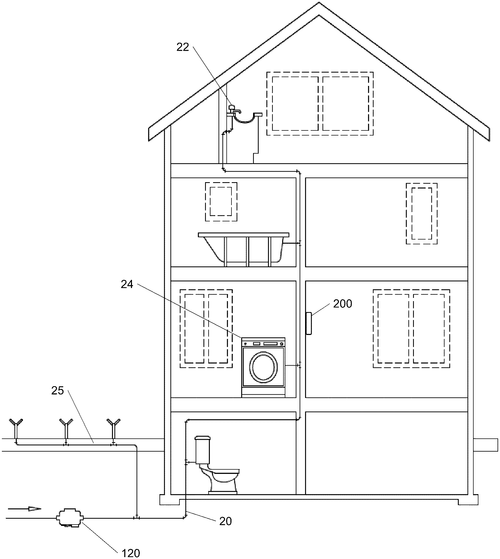
A recent patent application outlines a promising system for monitoring and reporting water consumption. This technology includes a sensor that detects fluctuations in a water meter's field, allowing it to track and analyze water events and identify their sources. By determining start time, end time, volume, and cadence associated with these events, the system can provide valuable insights into water usage patterns. The system goes beyond simply monitoring and reporting by incorporating a "decisioning engine." This engine determines the appropriate course of action following the identification of a water event. Possible actions range from simple notifications and alerts to updating a budget or aggregating information for further analysis. In a world where water scarcity and conservation are pressing concerns, this patent application offers a potential solution to better understand and manage water consumption. By detecting and analyzing fluctuations in water usage, individuals and organizations could identify leaks, track usage habits, and make informed decisions regarding water conservation. Competitor products in this market include smart water meters that focus on providing real-time consumption data and remote monitoring. However, this new system stands out with its ability to correlate water events with specific sources, providing a more comprehensive approach to water monitoring. Imagine the potential applications of this technology – municipalities could detect leaks in their water systems quicker, homeowners could identify wasteful habits and adjust accordingly, and businesses could optimize their water usage practices. The possibilities are vast and could contribute to a more sustainable future. But as always, it's important to consider the practicality of translating a patent into a viable product. While the concept holds promise, the patent application does not provide details about the system's feasibility or potential limitations. Ultimately, it will be interesting to see if this invention will be developed into a fully functioning system that can make a meaningful impact on water conservation efforts. What are your thoughts on this new system for monitoring and reporting water consumption? Do you see it as a valuable tool for water conservation, or do you have concerns about its implementation? Share your insights in the comments below.
The system provides a way to monitor and report water consumption, by detecting fluctuations in the field associated with a water meter. These fluctuations can be used to correlate one or more water events with their source(s), such as by determining a start time, end time, volume, and/or cadence. This information is then parsed out to identify fingerprints associated with various water events. The decisioning engine then determines one or more courses of action following identification of one or more water event fingerprints. These actions can include triggering or invoking system functions such as providing an alert or notification, flagging or otherwise reporting information, updating a budget, aggregating information, etc.
US Patent 11821766
****
Mass Flow Sensor Assembly: Capillary Tube Received In Arc-Shaped Grooves
What is this invention?
Mass flow sensor assembly and method of manufacturing a mass flow sensor assembly
A mass flow sensor assembly made,
Capillary tube and corners laid,
Arc-shaped grooves that hold the tube tight,
The method of manufacturing is quite bright.
It's a clever invention indeed to see,
That makes measuring mass flows so easy!
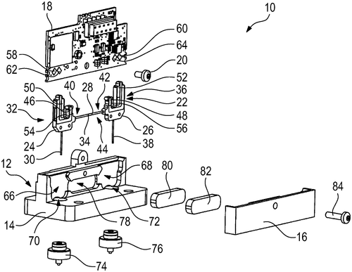
A newly published patent describes a promising development in the field of mass flow sensors. The invention proposes a mass flow sensor assembly for use in mass flow controllers or mass flow meters. The assembly consists of a capillary tube that holds a sensor portion, with the tube being supported by two corner supports, each featuring an arc-shaped groove to accommodate the tube. This innovation could potentially revolutionize the accuracy and efficiency of mass flow measurement in various industries. By utilizing separate corner supports for the capillary tube, the sensor portion is able to be precisely located between the two supports, enhancing the reliability of the measurements taken. While this patent showcases a significant advancement in mass flow sensor technology, it is important to note the competitive landscape. Various companies already offer mass flow controllers and meters with their own sensor configurations. As such, the potential impact of this specific invention on the market remains uncertain. However, the implications of a more precise and reliable mass flow sensor assembly are far-reaching. It could lead to improved control of mass flow in manufacturing processes, more accurate environmental monitoring, and enhanced gas flow management in medical equipment. The patented method of manufacturing the mass flow sensor assembly is not detailed in this publication, leaving room for speculation about the complexity and feasibility of production. Developing a reliable manufacturing process will be crucial for this invention to transition from a patent to a viable product. While we eagerly anticipate the realization of this new mass flow sensor assembly, we invite our readers to share their thoughts. How do you envision this technology being put to use in industries that rely on precise gas flow control? Could this innovation raise the bar for mass flow measurement accuracy?
The mass flow sensor assembly includes a capillary tube with a sensor portion located between the two corner supports. The corner supports each have an arc-shaped groove that partially receives the capillary tube. The method of manufacturing the mass flow sensor assembly is also described.
US Patent 11821776
****
A Pressure Measuring Device That's Configured As A Multi-Function Device Operable As A Differential Pressure Switch (DPS), A Differential Pressure Tra
What is this invention?
System and methods for a multi-function pressure device using piezoelectric sensors
A multi-function device was found,
It measured pressure all around.
It had two sensors and a PLC,
Retrofittable for thee and me.
Remote access made it sound!
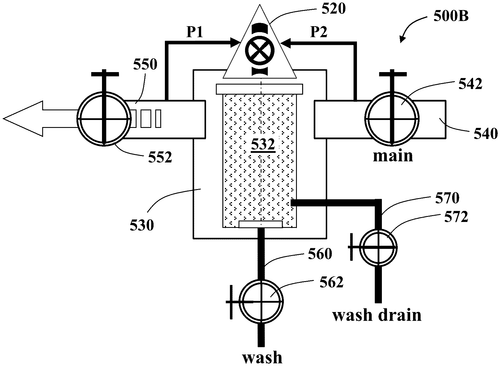
A recent patent describes a promising pressure measuring device that may revolutionize the industry by offering a range of functionalities. The device, which can be retrofitted, is designed to operate as a differential pressure switch (DPS), a differential pressure transducer (DPT), a pressure switch (PS), a pressure transducer (PT) providing readings of high and low pressure zones, a data recording logger, and a backwashing controller. One standout feature of this device is its use of piezoelectric sensors to measure pressure attributes, ensuring accuracy and reliability. Additionally, the electronic hardware, processing unit, cables, and pressure tubing are packaged within a molded case, eliminating the need for any moving parts. This not only enhances the device's durability but also enables it to withstand extreme environmental conditions. With the device fully coated, users can rely on its robustness even in harsh settings. The remote access capability is another highlight of this invention. Users can conveniently configure, maintain, and service the device remotely, saving time and effort. Furthermore, it offers seamless communication with external devices such as tablets and smartphones, providing a user-friendly interface. Moreover, it features a wired interface with a programmable logic controller (PLC) via RS-485 interface, enhancing its compatibility with existing systems. Considering its multi-functionality and innovative design, this pressure measuring device holds great promise for industries requiring accurate pressure measurement and control. However, it is important to note that this is a patent description, and not all patented inventions make it to the production stage. It would be interesting to see whether this technology will be further developed into a market-ready product. What are your thoughts on the potential uses of such a device? Would you find it useful in your industry? Share your opinions in the comments below.
This pressure measuring device is a multi-function device that can be used as a differential pressure switch (DPS), differential pressure transducer (DPT), pressure switch (PS), and pressure transducer (PT). The device has two piezoelectric sensors that are able to measure pressure attributes. The electronic hardware, processing unit, cables, and pressure tubing are retrofittable and packaged in a molded case with no moving parts. The device is configured for remote access, enabling remote device configuration, maintenance, and servicing. The device also has a wired interface with a programmable logic controller (PLC) via RS-485 interface.
US Patent 11821802
International Business Machines Corporation
A Method, Computer Program Product, and System to Address Vision-Related Issues
What is this invention?
Vision improvement utilizing computer displays
A system that tracks eye movements too,
It can detect vision-related issues like flu.
Analyzing data to determine probability,
Generates two dimensional visual exercise with agility.
The GUI then displays the exercise for you!
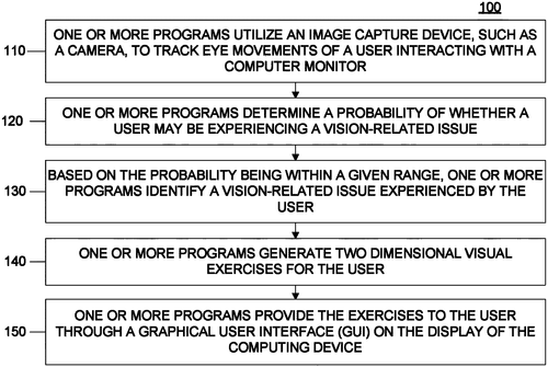
A recent patent application by International Business Machines Corporation (IBM) has caught the attention of tech enthusiasts and medical practitioners alike. The patent outlines a method, computer program, and system that utilizes an image capture device to track the eye movements of a user interacting with a display. The concept behind this innovation is to continuously collect image data and analyze it to determine the probability of a user experiencing a vision-related issue. If the probability falls within a predetermined range, the system then identifies the specific vision-related issue the user may be facing. Based on this identification, the system generates a two-dimensional visual exercise that aims to address the particular issue. The generated visual exercise is presented to the user via a graphical user interface deployed on the display. This user-friendly interface is designed to make the exercise easily accessible and engaging. By leveraging these technologies, the patent suggests that it could potentially provide a novel way to address vision-related issues and improve visual health. While IBM's patent application showcases a fascinating application of image capture and analysis technologies, it is crucial to consider the practical implications and challenges of turning this concept into a successful product. The patent does not provide details on the accuracy or effectiveness of the system in addressing vision-related issues, leaving room for skepticism. Competitor products, such as eye-tracking devices and vision training apps, already exist in the market, offering similar functionalities. Therefore, IBM would need to differentiate its product by showcasing its unique capabilities and the potential benefits it offers over existing alternatives. Furthermore, the patent does not delve into the technological requirements or potential limitations of this system. Implementing such a complex solution, which involves constant eye tracking and real-time analysis, could present significant technical challenges. In conclusion, while IBM's patent application outlines an intriguing concept for addressing vision-related issues through visual exercises, it raises questions about the practicality and feasibility of such a product. It remains to be seen whether IBM can overcome the technical complexities and establish a competitive advantage over existing solutions in this space. What are your thoughts on this patent application by IBM? Do you think this approach to addressing vision-related issues shows promise, or is it too ambitious to be realized effectively? Let us know in the comments below.
The text describes a method, computer program product, and system for tracking eye movements of a user. The system continuously collects image data and analyzes the data to determine a probability of whether the user may be experiencing a vision-related issue. Based on the probability being within a given pre-determined range, the system identifies the vision-related issue experienced by the user. The system then generates a two dimensional visual exercise to address the vision-related issue for performance by the user. Finally, the system deploys a graphical user interface to display the visual exercise to the user.
US Patent 11822073
International Business Machines Corporation
Testing Video-Based User Interface Applications Easily and Quickly
What is this invention?
Video-based user interface application testing
A text described methods, so neat
For UI application testing complete
Generate a third UI, the task at hand
Where user inputs will be scanned
To create test video images that can meet.
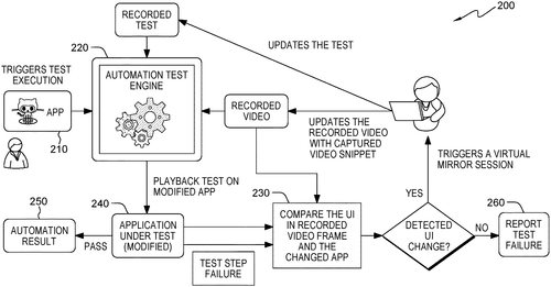
International Business Machines Corporation has recently filed a patent for a video-based user interface (UI) application testing method. This invention aims to improve the testing process of UI applications by utilizing video data. The method involves receiving test video data of an application running on a UI, and displaying the test video images on one screen while generating application video images on another screen. By comparing frames from both video streams, the system can identify instances where the test video images do not meet a predetermined similarity threshold with the application video images. In such cases, the invention generates a new UI on a third display, capturing replacement test video images for a specific duration while receiving user inputs. These replacement frames are then used to generate a new set of test video images, effectively replacing frames that failed to meet the similarity threshold. While the patent outlines a potentially useful tool for UI application testing, it remains to be seen how practical and commercially viable this invention will be. It is worth noting that there are already established competitors in the market that offer similar solutions. If implemented successfully, this invention could be of interest to companies developing UI applications, as it could potentially streamline the testing process and improve the overall user experience. However, questions remain regarding the efficiency, cost, and compatibility of this method with existing systems. How do you envision incorporating video-based UI application testing in the future? Do you believe it has the potential to revolutionize the testing industry? Share your thoughts in the comments below.
This text describes methods, computer program products, and computer systems for video-based user interface (UI) application testing. The method includes receiving first test video data corresponding to test video images of an application executing on a first UI, generating the test video images on a first display, generating application video images on a second display. Further, the method may include determining that a first frame of the test video images and a second frame of the application video images fail to satisfy a predetermined similarity threshold. The method then generates a third UI comprising the second frame of the second UI on a third display. Finally, user inputs are received at the third UI for a first duration. Replacement test video images are captured from the third display for the first duration and used to generate second test video images.
US Patent 11822464
International Business Machines Corporation
Database Self-Diagnosis and Self-Healing: New Processor Classifies Problem Description into Natural Language, Database Know-Who Content
What is this invention?
Database self-diagnosis and self-healing
A processor received a problem to solve,
It split it into two distinct parts - one that involved the database know-who and another with natural language processing techniques.
It combined results of both and then identified a solution,
And used it to solve the problem without any dissolution.
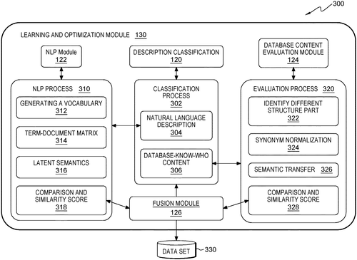
In a recent patent application, International Business Machines Corporation (IBM) has introduced an intriguing approach for database self-diagnosis and self-healing. The invention seeks to address the complex task of identifying and resolving issues within a database. According to the patent description, the proposed solution involves a processor that receives a problem description associated with a database. The processor then divides the problem description into two parts: a natural language description portion and a database-know-who content portion. By employing natural language processing techniques, the processor analyzes the natural language description to gain a better understanding of the problem at hand. Simultaneously, the processor evaluates the database-know-who content portion, although the specific details of this process were not disclosed. The result of both evaluations is then combined to generate a comprehensive understanding of the problem. Based on this combined result, the processor determines a solution and proceeds to solve the database issue. While the concept of database self-diagnosis and self-healing is not entirely new, this patent application from IBM offers a unique approach by incorporating natural language processing. This suggests that the technology could potentially understand and analyze problem descriptions described in plain language, allowing for more efficient and user-friendly troubleshooting. However, it's important to note that receiving a patent is not a guarantee that the technology will be transformed into a viable product. Many patented ideas remain purely theoretical or fail to overcome the challenges of practical implementation. Additionally, similar products in the market, such as database management systems with automated diagnostics and repair features, may pose competition to IBM's invention. Nevertheless, the potential applications of this technology are vast. Imagine database administrators being able to simply describe an issue in natural language, and the system automatically identifies and resolves the problem. This could greatly streamline the troubleshooting process and save valuable time and resources in various industries. As always, it remains to be seen whether this patent from IBM will materialize into a tangible product. Still, the concept of leveraging natural language processing for database self-diagnosis and self-healing is undeniably intriguing. What are your thoughts on this invention? Do you believe it could revolutionize database management or encounter significant challenges? Share your insights in the comments below.
A processor receives a problem description related to a database. The processor classifies the problem description into a natural language description portion and a database-know-who content portion. The processor processes the natural language description portion using natural language processing techniques. The processor evaluates the database-know-who content portion. The processor combines a result of processing the natural language description portion and evaluating the database-know-who content portion. The processor identifies a solution based on the problem description and the combined result. The processor solves a problem using the identified solution
US Patent 11822528
International Business Machines Corporation
Manage Knowledge Graph Updates with New Computer-Implemented Method
What is this invention?
Knowledge graph update using change layers
A computer-implemented plan
For knowledge graph updates began.
It built sub-regions, classified changes,
Created change layers to arrange
So the updated graph could be managed more effectively than!
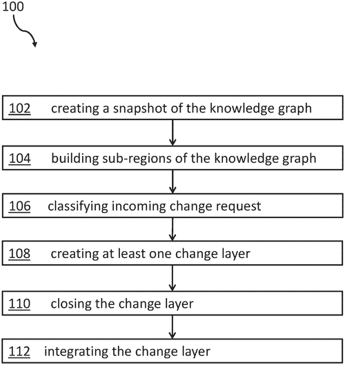
In a recent patent application by International Business Machines Corporation, a computer-implemented method for managing updates to a knowledge graph with incoming change requests has been unveiled. The method promises to revolutionize the maintenance and integration of knowledge graphs, providing a more efficient and streamlined approach. The patent suggests a multi-step process for managing updates to a knowledge graph. First, a snapshot of the existing graph is created as a reference point. Sub-regions of the graph are then built, allowing for better organization and categorization of information. Each incoming change request is carefully classified to ensure it corresponds to the relevant sub-region. This classification enables the creation of change layers, which are specific to each sub-region and consist of portions of the incoming change requests. A notable feature of this method is the ability to close a change layer once it reaches a predetermined threshold value. By doing so, the integration of the change layer into the knowledge graph becomes more efficient, reducing the overall processing time. Ultimately, this process generates an updated knowledge graph that reflects the implemented changes. While this patent showcases an innovative approach to managing knowledge graph updates, its practicality as a marketable product remains to be seen. Currently, there are several competitor products available in the market that offer similar functionalities, and it would be interesting to see how IBM's method differs in terms of performance, scalability, and usability. Looking ahead, potential uses for this patent range from knowledge databases used in research institutions and universities to data-driven decision-making systems in large organizations. The ability to efficiently manage and update knowledge graphs is crucial in these contexts, as it ensures the most up-to-date and accurate information is available to users. In conclusion, IBM's patent application presents a promising method for managing updates to knowledge graphs. However, its viability as a marketable product and its potential superiority compared to existing solutions are yet to be determined. What do you think? Would you find a tool like this useful in your industry? Let us know in the comments below.
The computer-implemented method for managing updates to a knowledge graph with incoming change requests is disclosed. The method comprises creating a snapshot of the knowledge graph, building sub-regions of the knowledge graph, classifying each incoming change to the knowledge graph so that it relates to one of the sub-regions, creating at least one change layer, wherein each of the at least one change layer relates to one of the sub-regions, wherein each of the at least one change layer comprises a portion of the incoming change requests, closing the at least one change layer upon reaching a predetermined threshold value for the at least one change layer, and integrating the at least one change layer into the knowledge graph. This results in an updated knowledge graph that can be used to manage changes more effectively.
US Patent 11822533
International Business Machines Corporation
Shared data is managed for use by shared materialized views - so changes to the primary data and creation of new views are fast and easy!
What is this invention?
Updating shared and independent materialized views in a multi-tenant environment
A view selector is quite wise,
It manages data updates and ties.
Shared materialized views
Are maintained through the news,
Distinguished from independent views in size.

IBM has recently filed a patent for a system that aims to revolutionize data management and storage. The proposed technology introduces the concept of shared materialized views, which can be maintained during data changes and creation of new views. In simpler terms, this technology offers a way to efficiently store and update data that is used by multiple views or perspectives. By distinguishing between shared and independent materialized views, this system can effectively manage data updates and ensure the proper movement of information between these views. The potential applications for this technology are vast. Imagine a company with multiple departments, each requiring access to the same data but from different perspectives. With shared materialized views, these departments can simultaneously access and analyze the data they need without duplication or confusion. This could streamline operations and foster greater collaboration within organizations. Competitors in the data management industry already offer similar solutions, such as shared databases and data replication technologies. However, IBM's patented system appears to offer a unique approach by specifically focusing on the management and maintenance of materialized views. While this patent is undoubtedly a significant development in the field of data management, it's worth considering the practicality of implementing such a system. Transitioning from existing data management solutions to this new paradigm might require significant effort and resources. The potential benefits should be carefully weighed against the potential challenges and costs of adoption. That being said, this patent raises an interesting question: How would this new system impact industries that heavily rely on complex data analysis and multi-perspective views? Can you think of any industries that could benefit the most from this technology, or potential drawbacks that might hinder its widespread adoption? Share your thoughts in the comments below.
Shared materialized views are maintained during data changes to the primary data and during creation of new materialized views. Shared data stored for use by shared materialized views is distinguished from data stored by an independent materialized view. A view selector manages data updates to shared materialized views and corresponding mapping table. The view selector directs movement of data between a shared materialized view and an independent materialized view through the lifecycle of the materialized views.
US Patent 11822547
Apple Inc.
Images from a Display System Coupled into a Waveguide are Multiplexed and Output to the User
What is this invention?
Head-mounted display system
A head-mounted display device
With a waveguide and image planes,
It has multiplexing techniques too,
For the user to view it's true.
The input and output couplers all say "Hooray!"

Apple has recently been granted a patent for an intriguing new invention—a head-mounted display that produces images in multiple planes. The system uses pixel arrays, such as liquid-crystal-on-silicon pixel arrays, to generate the images, which are then transmitted into a waveguide through an input coupler system. The waveguide, in turn, emits the images in multiple planes by employing an output coupler system. To achieve this, the patent discusses various techniques, ranging from multiplexing with different wavelengths and polarizations to time-division multiplexing and tunable lens techniques. While the concept of a head-mounted display is not entirely new, Apple's patent suggests a notable advancement by enabling the presentation of images in multiple image planes. This has interesting implications for virtual and augmented reality applications, as it could potentially enhance the immersion and realism experienced by users. Imagine wearing Apple's head-mounted display and being able to see virtual objects not just in the forefront, but also in the background or at different depth levels—talk about an even more immersive experience! As with any patent, it's important to remember that not all ideas make it into actual products. Nonetheless, Apple's ongoing work in the field of augmented and virtual reality, coupled with this recently granted patent, suggests they are actively exploring new technologies to improve user experiences. Other companies, like Microsoft and their HoloLe. ns, and Facebook with their Oculus, are also advancing in this area, fierce competitors that will surely drive innovation. What do you think about the potential of this technology? Do you believe we will soon see head-mounted displays with multi-plane imaging hit the market? Share your thoughts in the comments below.
This text describes an electronic device, such as a head-mounted display, that has a display system that produces images. Images from the display system may be coupled into a waveguide by an input coupler system and may be coupled out of the waveguide in multiple image planes using an output coupler system. The input and output coupler systems may include single couplers, stacks of couplers, or tiled arrays of couplers. Multiplexing techniques such as wavelength multiplexing, polarization multiplexing, time-division multiplexing, multiplexing with image light having different ranges of angular orientations, and/or tunable lens techniques may be used to present images to a user in multiple image planes.
US Patent 11822078
Apple Inc.
New Display Technology Provides Image and World Light to a Waveguide
What is this invention?
Waveguided display system with adjustable lenses
A device with two lenses was made,
One for light and one to fade.
The first lens had angles set apart,
And the second had corresponding start.
For world light it will allow, image power it'll disavow!
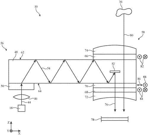
In a recent patent from Apple Inc., a new invention promises to enhance the viewing experience on electronic devices. The patent describes an electronic device equipped with a display that utilizes a waveguide to provide image light. To further optimize the viewing capabilities, the device includes two liquid crystal lenses mounted on opposing surfaces of the waveguide. The first lens is responsible for coupling the image light out of the waveguide, while the second lens conveys the world light to the first lens. This setup allows the control circuitry to manipulate the optical power of both the image and world light. By applying a second optical power to the world light that cancels out the first optical power, the device can achieve a more seamless viewing experience. The patent goes into detail about the design of the lenses, explaining that each lens consists of two layers of liquid crystal molecules with antiparallel pretilt angles. The pretilt angles and rubbing directions of the first lens are intentionally set to be antiparallel to those of the second lens around the waveguide. While this patent is undoubtedly intriguing, it is important to note that not all patented technologies end up becoming actual products. It is still uncertain whether this innovation will make its way into future Apple products or if it will remain solely a concept on paper. Competitors in the market, such as Samsung and LG, have been pushing the boundaries of display technologies. It remains to be seen if Apple's approach can compete with their offerings or bring something truly groundbreaking to the table. Considering the potential applications, this technology could significantly enhance the display quality on electronic devices, improving the overall user experience. It signifies Apple's continuous efforts to innovate and stay ahead in the highly competitive tech industry. What are your thoughts on this latest patent from Apple? Do you believe this technology has the potential to revolutionize the way we view content on electronic devices? Share your insights in the comments below.
This text describes an electronic device that has two lenses - one that provides image light to a waveguide, and another that cancels out the image light's power. The first lens is designed to have antiparallel pretilt angles and rubbing directions, while the second lens has corresponding pretilt angles and rubbing directions about the waveguide. This combination allows for world light to be conveyed into the first lens while suppressing the power of image light.
US Patent 11822079
Apple Inc.
A New Way to Merge Reality with Display Images
What is this invention?
Display system with time interleaving
A head-mounted device with a display,
Produces an image to astound;
It merges the real world,
With images unfurled,
Using time interleaving and polarization 'round.
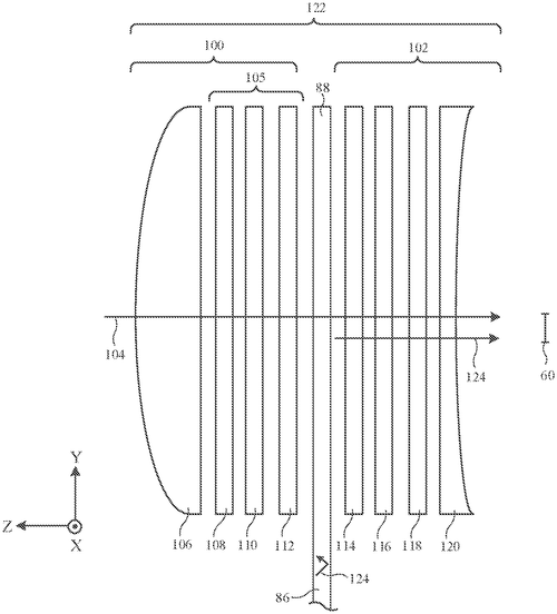
In a recent patent filed by Apple Inc., an electronic device is described that could potentially revolutionize the way we interact with technology. This device, described as a head-mounted device, features a display that produces a display image for the user. What sets this invention apart is the incorporation of an optical system that merges real-world images with the display images. Think of it as a window to a virtual world, where real-world objects seamlessly blend with digital content. The optical system provides these merged images to an eye box for users to view. To achieve this, the patent suggests the use of time interleaving techniques and polarization effects. Switchable devices, such as polarization switches and tunable lenses, can then be controlled in synchronization with the frames of the display images. Additionally, the patent mentions the use of geometrical phase lenses that exhibit different lens powers for different polarizations of light. Considering the growing market for augmented and virtual reality technologies, it's no surprise that Apple is exploring these possibilities. Competitors like Microsoft's HoloLe. ns and Facebook's Oculus have already made strides in the field, and it seems Apple wants to stake its claim. While the patent is exciting, it's essential to note that many patents never make it to the final stage of being turned into products. The technology described has the potential to transform the way we interact with digital content, but it remains to be seen if Apple will bring this invention to market. The potential applications for such a device are vast. From gaming and entertainment to educational and professional use cases, a head-mounted device that seamlessly integrates real-world and digital content could open up a myriad of possibilities. But what do you think? Would you be interested in a head-mounted device that merges real-world and virtual content? How do you envision using such technology in your daily life? Let us know in the comments below.
The text describes an electronic device, such as a head-mounted device, that has a display that produces a display image. The head-mounted device may have an optical system that merges real-world images from real-world objects with display images. The optical system provides the real-world images and display images to an eye box for viewing by a user. The optical system may use time interleaving techniques and/or polarization effects to merge real-world and display images. Switchable devices such as polarization switches and tunable lenses may be controlled in synchronization with frames of display images. Geometrical phase lenses may be used that exhibit different lens powers to different polarizations of light.
US Patent 11822083
Apple Inc.
Privacy Film May Have Light-Blocking Layer That Is Interposed Between First and Second Transparent Substrates
What is this invention?
Privacy films for curved displays
A privacy film for a curved display,
Will have opaque portions that will not miss-play.
The light is blocked so it's directed only to one,
So the view of others can't be done.
This film has different angles and layers galore,
To ensure your viewing is secure evermore!
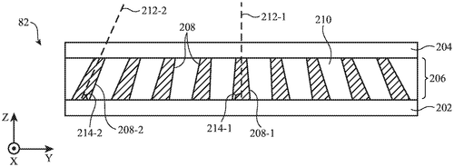
Apple Inc. has recently filed a patent for a privacy film that aims to revolutionize the way we protect our displays. The patent describes a privacy film consisting of a light-blocking layer sandwiched between two transparent substrates. What sets this invention apart is its ability to direct light from the display only towards the primary viewer. Privacy films have been around for a while, with various manufacturers offering solutions to protect sensitive information on our screens from prying eyes. However, Apple's patent takes this concept a step further by ensuring that the display is only visible to the intended user. The opaque portions on the film are strategically shaped to block light from unwanted angles, guaranteeing privacy without compromising visibility for the person directly in front of the screen. Moreover, the patent reveals that this innovation is not limited to flat displays. The privacy film is designed to cover curved displays as well, accommodating screens with different angles and shapes. By incorporating a light-redirecting layer, such as a prism or liquid crystal layer, the film can effectively guide the light towards the primary viewer, regardless of the curvature of the display. While this patent showcases Apple's commitment to enhancing privacy and usability, it's important to remember that patents don't always translate into tangible products. Many patented technologies never see the light of day, which leaves us wondering if this privacy film will ever become a reality. Competitor brands have their own privacy solutions, with some offering specialized films and others opting for software-based privacy features. It will be interesting to see if Apple manages to bring this technology to market and how it will compare to what competitors already have to offer. Considering the potential applications of such a privacy film, one can imagine its usefulness in various settings. From corporate boardrooms to coffee shops, protecting sensitive information on our devices is becoming increasingly crucial. This technology could be a game-changer for professionals who frequently work on the go and need to keep their data secure, while still maintaining the convenience of a portable device. What are your thoughts on this patent? Do you think the privacy film described here will revolutionize the way we protect our screens, or do you believe it will end up being just another promising idea that never materializes? Share your opinions in the comments below.
The privacy film may have a light-blocking layer that is interposed between first and second transparent substrates. The light-blocking layer may have a plurality of opaque portions and a plurality of transparent portions. The opaque portions may be shaped to ensure light from the display is directed only to the primary viewer of the display. Each opaque portion of the light-blocking layer may extend along a respective longitudinal axis between the first and second transparent substrates. Privacy films used to cover curved displays may have opaque portions that extend along longitudinal axes that have different angles relative to the transparent substrates. Opaque portions in the edge of the privacy film may have longitudinal axes that are at non-perpendicular angles with respect to the transparent substrates. A privacy film for a curved display may also include a light-redirecting layer such as prism layer or liquid crystal layer
US Patent 11822103
Apple Inc.
Non-silicone adhesive helps avoid cracking and plastic deformation during drop events
What is this invention?
Lens mounting systems for electronic devices
A head-mounted device with a view,
The lenses were held by adhesive glue.
It had to be strong,
To avoid cracks and wrong,
And the elastic modulus made it true!
Apple Inc. has recently filed a patent for an intriguing development in the world of head-mounted display technology. The patent describes an electronic device, like a head-mounted device, that incorporates a display to present images to the user. This device also includes head-mounted support structures to hold the display and lenses in place. One notable feature mentioned in the patent is the use of adhesive to attach the lenses to the support structures. The adhesive plays a crucial role, as it needs to bond effectively while preventing cracking and plastic deformation during accidental drops. By utilizing a non-silicone adhesive that fractures in bulk rather than at the interfaces with lenses and support members, Apple aims to enhance the durability and resilience of the device. This invention could potentially impact the emerging market of head-mounted devices, particularly those used for virtual and augmented reality experiences. Competitors in this space, such as Oculus and Microsoft, have already released headsets with lenses that rely on different mounting mechanisms. Apple's new patent raises intriguing questions about the future of such technologies. How might the incorporation of these adhesive mechanisms improve the user experience of head-mounted displays? Will this patent translate into a real product that consumers can get their hands on? As always, only time will tell if and when this innovation will become a reality. In the meantime, we invite you, our readers, to share your thoughts on this development in the comments below. How do you foresee adhesive technology shaping the future of head-mounted devices?
An electronic device such as a head mounted device may have a display that displays an image for a user. Head-mounted support structures may be used to support the display and to support lenses. The head-mounted support structures may have one or more lens barrels or other support members. Each lens may have an optical surface and a side surface. Adhesive may be used to attach the lenses to the head-mounted support structures. A first portion of the adhesive may bond each lens to a first respective portion of a support member and a second portion of the adhesive may bond each lens to a second respective portion of the support member. The adhesive may be a non-silicone adhesive that fractures in bulk rather than failing at interfaces with the lens and support member. The elastic modulus of the adhesive may help avoid cracking and plastic deformation during drop events.
US Patent 11822145
CANON KABUSHIKI KAISHA
Zoom lens with seven fixed lenses offers versatility
What is this invention?
Zoom lens and image pickup apparatus
A zoom lens had seven parts in all
Each unit with a refractive power tall
The fourth to seventh lenses were fixed when zooming
While the adjacent ones kept moving and booming
This structure made the image quite small
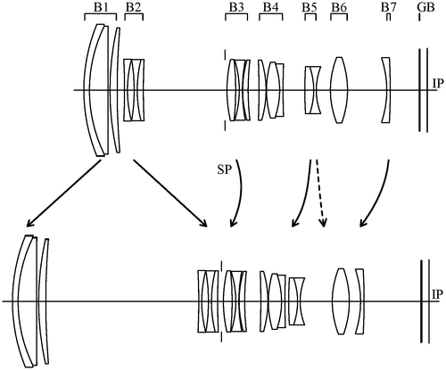
Canon, the renowned multinational corporation known for its cutting-edge imaging solutions, has recently filed a patent for a new zoom lens design. The patent describes a unique arrangement of lens units that promises to enhance the capabilities of future camera systems. According to the patent, this zoom lens configuration consists of seven lens units positioned in a specific order from the object side to the image side. This includes a combination of lens units with positive and negative refractive powers, each responsible for manipulating light in a precise manner. During the zooming process, the distance between adjacent lens units is adjusted, and specific lens units, such as the first, second, and select units from the third to seventh, are set in motion, while others remain fixed. While Canon's patent showcases a potentially innovative zoom lens concept, it is essential to note that not all patented ideas materialize into commercially available products. The competitive camera market is filled with similar patents from various manufacturers, all striving to bring enhanced features and superior imaging quality to photographers worldwide. If realized, this novel zoom lens could unlock new possibilities in the field of photography, enabling users to capture dynamic and detailed images with great flexibility. From professional photographers seeking versatility in their lenses to hobbyists looking to explore various focal lengths, the potential uses for this invention seem promising. However, the big question remains: Will Canon transform this patent into an actual product? Do you believe this zoom lens design has the potential to revolutionize the photography industry and elevate the capabilities of future cameras? Share your insights in the comments below.(Note: This review is based solely on the information present in the patent and does not indicate the definitive release or production of the described zoom lens by Canon.)
The zoom lens includes a first lens unit having a positive refractive power, a second lens unit having a negative refractive power, a third lens unit having a positive refractive power, a fourth lens unit having a positive refractive power, a fifth lens unit having a negative refractive power, an sixth lens unit having a positive refractive power, and seventh lens unit having a negative refractive power. During zooming, the distance between adjacent lens units changes and at least one of the fourth to seventh lenses is fixed.
US Patent 11822064
CANON KABUSHIKI KAISHA
Optical System with Moving Unit Keeps Image Steady
What is this invention?
Optical system and optical apparatus
A system of optics was designed,
With a concave and convex in mind.
The lens unit will move,
To adjust for the jive,
And keep images steady and aligned.
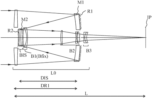
In a recent patent filed by Canon Kabushiki Kaisha, a new optical system is outlined that promises to enhance image stabilization capabilities in cameras. This optical system consists of a first optical element with a concave reflective surface facing the object side, a second optical element with a convex reflective surface facing the image side, and a lens unit positioned between the two. The concept is intriguing, as it suggests that light from the object would travel through the first reflective surface and then the second reflective surface before reaching the image plane. By incorporating a movable unit, which potentially includes either the second optical element or the lens unit, the technology aims to facilitate image stabilization. While the patent offers an interesting proposition for improving image stabilization, it is important to note that a patent is merely a legal protection for an idea and does not guarantee that a product incorporating this technology will actually be developed by Canon. It will be interesting to see if Canon can successfully transform this concept into a practical and marketable product that can compete against existing image stabilization solutions from competitors. Moreover, there are possibilities beyond cameras where this technology could potentially find applications. For instance, if the image stabilization mechanism is refined, it could be integrated into other devices such as drones, virtual reality headsets, or even surgical tools that require steady visuals. In conclusion, Canon's patent on an optical system with improved image stabilization capabilities piques curiosity, but it remains to be seen whether this concept will materialize into a marketable product. Would you be interested in a camera or device equipped with this advanced image stabilization technology? Let us know in the comments below!
An optical system includes a first optical element having a concave reflective surface that directs light towards an object side, and a second optical element having a convex reflective surface that directs light towards an image side. The first and second optical elements are disposed between the lens unit, which allows light to travel to the image plane through the first and second reflective surfaces in this order. A movable unit is configured to move during image stabilizing so that it can move either the second optical element or the lens unit relative to each other in order to adjust for jittery images.
US Patent 11822096
CANON KABUSHIKI KAISHA
An Optical Information Processing Apparatus for Better Photos
What is this invention?
Information processing apparatus, image capturing apparatus, information processing method, and storage medium
A device that processes info,
It has an obtaining unit three;
Optical information, orientation and installation direction
To control the lens in its section.
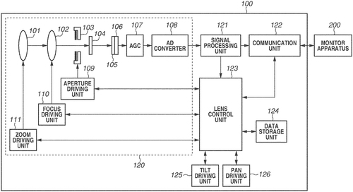
In a recent patent filed by Canon Kabushiki Kaisha, an innovative information processing apparatus has been introduced. This device is designed to enhance optical information processing for image capturing apparatuses, paving the way for more advanced photography and imaging technology. The patent describes an apparatus that includes three key components: a first obtaining unit, a second obtaining unit, and a control unit. The first obtaining unit is responsible for gathering optical information about an image capturing apparatus, specifically focusing on the imaging optical system, which comprises a movable lens capable of movement along the optical axis direction. The second obtaining unit collects orientation information related to the lens barrel that holds the imaging optical system. Lastly, the third obtaining unit acquires installation information, indicating the installation direction of the image capturing apparatus. The control unit acts as the brain of the apparatus, utilizing the gathered optical, orientation, and installation information to control the position of the movable lens. This innovative approach aims to optimize the overall imaging process, ensuring high-quality results and improved functionality. While this patent showcases Canon's commitment to advancing image capturing technologies, it's important to note that patents do not guarantee the development or release of a commercial product. Competitors in the market, such as Nikon and Sony, have their own ongoing research and development efforts, leveraging similar concepts to improve photography experiences. Thus, the existence of a patent alone does not determine whether this invention will become a consumer product. However, if realized, this information processing apparatus has the potential to revolutionize the way we capture images. By precisely controlling the position of the movable lens, users can expect enhanced image stabilization, advanced auto-focus capabilities, and improved overall image quality. Additionally, this technology could have applications beyond consumer photography, potentially benefiting industries such as medical imaging and surveillance. Considering the continuous advancements in camera technology and the ever-evolving demands of photographers and consumers as a whole, the question remains: How do you envision technologies like this shaping the future of photography and image capturing?
The text describes an information processing apparatus that includes a first obtaining unit configured to obtain optical information about an image capturing apparatus including an imaging optical system including at least one movable lens movable in an optical axis direction, a second obtaining unit configured to obtain orientation information indicating the orientation of the lens barrel holding the imaging optical system, a third obtaining unit configured to obtain installation information indicating the installation direction of the image capturing apparatus, and a control unit configured to control a position of the movable lens based on the optical information, orientation information, and installation information.
US Patent 11822148
CANON KABUSHIKI KAISHA
A Focus Adjustment Device Corrects Results of Autofocus
What is this invention?
Imaging optical system storing information on its aberration, imaging apparatus, and control method thereof
A focus adjustment device was made
To correct the autofocus result grade.
It took in astigmatism, chromatic aberration, too;
And a spherical aberration it knew.
Then it adjusted the lens position with skill,
For photos that were sharp and still!
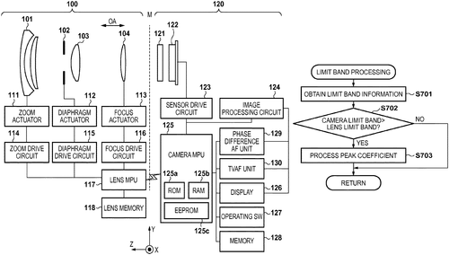
Canon has recently filed a patent for a focus adjustment device that aims to improve autofocus accuracy by accounting for optical aberrations in an imaging system. The patent describes a method in which a correction value is obtained from aberration information, including astigmatism, chromatic aberration, and spherical aberration, along with autofocus focus detection information. This correction value is then used to control the position of a focusing lens in the imaging optical system, resulting in a more accurate autofocus result. While this patent showcases Canon's commitment to advancing autofocus technology, it is important to note that not all patented inventions make it to the production stage. The camera market is fiercely competitive, with major players like Nikon and Sony constantly pushing boundaries with their own autofocus systems. The potential uses for such a focus adjustment device are undoubtedly exciting. Accurate autofocus is crucial in various photography genres, including sports, wildlife, and even portrait photography. By minimizing focus detection errors caused by optical aberrations, photographers can expect sharper and more precise images. However, it is also essential to consider the practicality and feasibility of implementing this technology in actual products. How would Canon integrate this focus adjustment device into their existing camera lineup? Would it require significant hardware changes or would it be a software-based enhancement? Could competitors develop similar solutions to address autofocus accuracy? As we await further developments from Canon, we invite you, our readers, to share your thoughts in the comments below. How important is autofocus accuracy for your photography needs? Would you be interested in a focus adjustment device that accounts for optical aberrations?
The focus adjustment device obtains a correction value for correcting a result of autofocus, from aberration information regarding at least one of an astigmatism, a chromatic aberration, and a spherical aberration of an imaging optical system. The focus adjustment device then controls a position of the focusing lens that the imaging optical system has, based on the corrected result of autofocus. By correcting the result of autofocus while considering at least a focus condition of a photographic image, an error in focus detection caused by an aberration in the optical system can be accurately corrected.
US Patent 11822211
CANON KABUSHIKI KAISHA
Lenses that connect directly!
What is this invention?
Lens apparatus and imaging apparatus having the same
A lens apparatus so fine
Had a first barrel and fixed one in line
It had an actuator too,
And a positioning mech to view
To make sure the focus was just divine
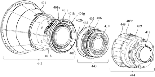
Canon has recently filed a patent for a lens apparatus that could potentially revolutionize the field of photography. The apparatus comprises a first barrel that holds a first lens unit, a fixed barrel that holds a final lens unit, a focus lens unit driven by an actuator, and a positioning mechanism which determines the rotational positions of the first and fixed barrels around the optical axis. What sets this patent apart is the direct connection between the first and fixed barrels, as well as the inclusion of the actuator and focus lens unit within the space formed by these barrels. While the patent description is quite technical, its implications are intriguing for both amateur and professional photographers alike. By eliminating the need for additional supporting structures or complicated mechanisms, Canon's lens apparatus could potentially result in a more lightweight and compact lens design. This could mean greater portability and convenience for photographers, allowing them to capture high-quality images without the burden of carrying heavy equipment. It is important to note that the existence of a patent does not guarantee that the invention will become a commercial product. Canon, like many other technology companies, regularly files patents as part of their ongoing research and development efforts. Therefore, it remains to be seen whether this lens apparatus will ever become a reality. In the competitive world of camera lenses, other manufacturers such as Nikon and Sony have also been pushing the boundaries of innovation. Nikon's recent release of a lens with an electric diaphragm control system and Sony's advancements in lens stabilization technology are just a few examples. However, Canon's patent hints at a unique approach that could potentially disrupt the market if successfully implemented. Now, we turn to you, dear readers. What are your thoughts on Canon's lens apparatus patent? Do you think the concept has the potential to become a game-changer in the world of photography? Share your insights and opinions in the comments below!
This lens apparatus includes a first barrel that holds a first lens unit, a fixed barrel that holds a final lens unit, an actuator that drives the focus lens unit, and a positioning mechanism that determines positions of the first barrel and the fixed barrel in a rotational direction around an optical axis. The first barrel and the fixed barrel are directly connected, and the actuator and the focus lens unit are provided in a space formed by the first barrel and the fixed barrel.
US Patent 11822214
Dell Products L. P.
A Portable Information Handling System with Aesthetic Edge-To-Edge Display and Access to Underlying Sensors
What is this invention?
Edge-to-edge display with a sensor region
A portable information system had a plan
To present visuals edge-to-edge on one side, then
The inactive portion of the display panel was sealed
So that illumination could not be revealed.
With index matching resin and black matrix in place, its beauty won't be denied by any face!
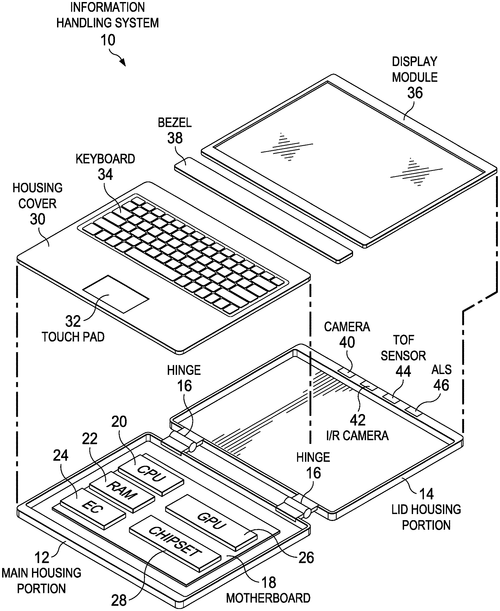
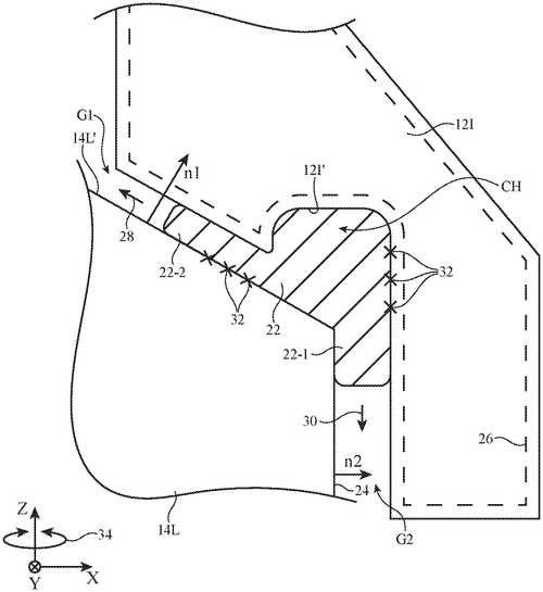
Dell Products L. P. has recently filed a patent for a portable information handling system, which boasts an impressive edge-to-edge presentation of visual images. This innovative housing design integrates a display that seamlessly extends to the edges, creating a captivating visual experience. One notable feature is the inclusion of an inactive portion of the display panel along the perimeter, which houses a sensor region allowing access to underlying sensors through the screen. To enhance user experience and aesthetics, Dell employs a combination of sealant and black matrix in the inactive region. This clever addition limits the escape of illumination from the active display area, resulting in a visually pleasing edge-to-edge appearance. Furthermore, specialized openings in the sealant and black matrix at sensor locations facilitate access through the display, utilizing index matching resin to pass illumination while maintaining a patterned covering of the black matrix. The potential uses for such technology would be far-reaching, particularly in the realm of portable devices like tablets and smartphones. Providing users with an immersive display that stretches from edge to edge could enhance the viewing experience for movies, gaming, and other media consumption. The seamless integration of sensors within the display also holds promise for improved touch functionality and overall device performance. As exciting as this patent sounds, it is important to remember that not all innovative ideas translate into successful products. While Dell's edge-to-edge display concept is intriguing, it remains to be seen whether the technology will be implemented into a commercial device. Competitors in the market, such as Apple and Samsung, have already made strides in minimizing bezels and maximizing screen real estate on their latest devices. Dell would need to demonstrate significant advancements or unique selling points to disrupt the status quo. In light of Dell's patent filing, one question arises: How important is the edge-to-edge display feature to you when considering a new portable device? Would you be willing to sacrifice other aspects, such as battery life or durability, for a seamless and immersive visual experience? Share your thoughts in the comments below.
The text describes a portable information handling system that has an edge-to-edge presentation of visual images on one side and an inactive portion of the display panel along the perimeter with sensor regions that provide access to underlying sensors. The sealant and black matrix disposed in the inactive region limits illumination that escapes from the active region, providing an aesthetically appealing edge-to-edge appearance. Openings in the sealant and black matrix at the sensor locations provides access through the display, such as with index matching resin that passes illumination and a patterned covering of the black matrix.
US Patent 11822193
Dell Products L. P.
Wireless Charging for Tablets: Magnetic Attraction Keeps Devices Close Together
What is this invention?
Magnetic coupling and de-coupling of a tablet information handling system to a stand
A tablet with magnets quite bold,
To hold a receiver of gold.
When rotated just right,
The attraction takes flight,
And the wireless charging can be controlled.
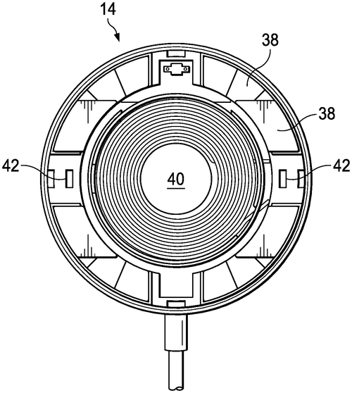
In the competitive world of tablets, companies are constantly searching for innovative ways to improve the user experience. Dell Products L. P. seems to have taken a step in the right direction with their recently published patent for a tablet information handling system. This system selectively couples to a charging stand and charging dock using magnets to hold a wireless charging receiver aligned with a wireless charger. What sets this patent apart is the clever use of opposing sets of spaced magnets. When the tablet is coupled in a landscape or portrait orientation, the magnetic attraction between the magnets is at its strongest, ensuring a secure connection for wireless charging. However, when it's time to remove the tablet, a simple rotation to an offset orientation reduces the magnetic attraction, making it easier to separate the device from the charging stand or dock. To ensure the user is aware of the correct positioning for separation, a sensor is cleverly placed in one of the spaces. This sensor detects the increased magnetic flux when the magnet aligns with the space, triggering a notification through the device's user interface. This handy feature provides a helpful indication to the end user that the tablet is positioned correctly for detachment. While this patent sounds promising, it's important to remember that not all patents see the light of day as actual products. Competitors in the tablet market, such as Apple and Samsung, already offer their own wireless charging solutions, so it remains to be seen whether Dell will follow through and release a tablet with this magnetic-based system. Nevertheless, if Dell's patent were to become a reality, it could offer users a more convenient and intuitive way to charge their tablets. Imagine having peace of mind that your tablet is securely connected to the charging stand or dock, without the hassle of aligning charging pins or cables. So, what do you think? Would you welcome a tablet with this magnetic-based charging system or do you prefer the current solutions available on the market? Let us know in the comments below.
The text describes a tablet information handling system that has magnets to hold a wireless charging receiver in place. When the tablet is rotated so that the magnets are aligned with opposing spaces, the attraction between them is reduced, allowing the receiver to be removed.
US Patent 11822387
Dell Products L. P.
Keep Your IHS Cool with Our New Thermal Window
What is this invention?
Thermal window for information handling system (IHS) housing
A thermal window for an IHS
Comes with a plate of metal and plastic, too;
The hot spot to cool off,
It's the perfect way off--
Just like it was meant to do!
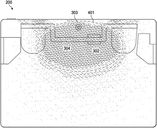
Dell Products has recently been granted a patent for a system that aims to provide a thermal window for an Information Handling System (IHS) housing. The patent describes a solution where the housing of an IHS, which typically consists of various components, includes a plate with both metal and plastic portions. This design positions the plastic portion of the housing adjacent to a hot spot on the IHS, potentially allowing for better temperature regulation. While this patent showcases Dell's innovation in addressing thermal issues in electronic devices, it is worth noting that the mere granting of a patent does not guarantee that the invention will become a tangible product anytime soon. Many patents are filed by companies as a means to secure their intellectual property, without concrete plans for bringing them to market. It is uncertain whether Dell intends to develop this technology further or if it is simply exploring potential solutions to thermal challenges. In the competitive market of information handling systems, companies like Dell are constantly striving to enhance device performance and user experience. Temperature regulation is a critical aspect, as excessive heat can degrade performance and shorten the lifespan of electronic components. Although Dell has not announced any concrete plans to implement this patent, it is evident that the company is actively exploring ways to address thermal issues within their product lineup. Considering the potential applications, this thermal window technology could have implications beyond Dell's IHS housing. Various electronic devices, such as laptops, desktops, gaming consoles, and even servers, could benefit from improved thermal management. If successfully implemented, this innovation might pave the way for a more efficient and durable generation of electronic devices. However, it remains to be seen if Dell will utilize this patent. The question we pose to you, dear readers, is: Do you believe this thermal window technology has the potential to revolutionize the way we manage heat in electronic devices? Let us know your thoughts in the comments section below.
Embodiments of systems and methods for providing a thermal window for an Information Handling System (IHS) housing are described. In some embodiments, an IHS may include a plurality of components and a housing configured to hold the plurality of components, where the housing includes a plate having a metal portion and a plastic portion, and where the plastic portion is positioned adjacent a hot spot of the IHS. The metal portion may be configured to dissipate heat from the hot spot.
US Patent 11822393
Dell Products L. P.
Portable Information Handling System Keyboard Features Variable-Feel Response to User Experience
What is this invention?
Information handling system variable feel input device
A keyboard that's quite unique and sublime
Is equipped with a spring in each key prime
The magnetic-rheological fluid
Controls the range of motion viewed
It's adjustable to suit your time
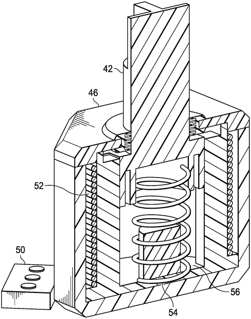
Dell Products L. P. has recently patented a new portable information handling system keyboard that promises to revolutionize the way we interact with our devices. This innovative keyboard features plural keys with a programmable variable-feel response, adapting to the end user's experience in real time. One fascinating aspect of this invention is the use of magnetic-rheological fluid within each key. As the user presses a key, a piston moves downward, allowing the fluid to pass through openings. In response to a biasing mechanism, such as a spring, the piston moves upward, providing tactile feedback. By applying current to a coil surrounding the chamber, a magnetic field alters the viscosity of the fluid, ultimately programming the key's compression, range of motion, and movement to a raised position. While the potential applications of this technology are vast, it remains to be seen whether Dell will successfully incorporate it into a marketable product. Competitors in the market, such as Logitech and Microsoft, already offer keyboards with customizable key responses, so Dell has stiff competition to handle. However, if successfully implemented, this invention could greatly enhance typing experiences for users across various industries. From gaming enthusiasts craving responsive keystrokes to professionals seeking a comfortable typing experience, this programmable variable-feel keyboard has the potential to cater to a wide range of needs. But before we get too excited, we should remember that patents do not always guarantee the production of a commercial product. Many factors, including cost, consumer demand, and technological feasibility, must align for this invention to become a reality. Overall, Dell's recent patent presents a compelling concept that could transform the way we interact with our devices. Will Dell take the initiative to bring this keyboard to market? Would you be interested in using a keyboard with programmable variable-feel responses tailored to your preferences? Let us know your thoughts in the comments below.
The text describes a portable information handling system keyboard that includes plural keys that each have a programmable variable-feel response to an end user experience with key interactions in real time. The magnetic-rheological fluid is disposed in a chamber of the key and passes through openings formed in the piston that moves downward with a keypress and upward in response to a biasing mechanism, such as a spring disposed in the chamber. Current applied to the coil around the chamber creates a magnetic field that varies the viscosity of the fluid so that key compression and range of motion associated with an input as well as key movement to a raised position are programmable to adjust based upon sensed key position and movement.
US Patent 11822394
Dell Products L. P.
Graphene-Painted Electronic Device Shield Keeps Your Gear Cool
What is this invention?
Information handling system thermal and EMI enclosures
There was a device that ran too hot,
So an EMI shield they did plot.
It had a frame coupled to the board,
And a separate shield with graphene paint poured.
The excess thermal energy it would reject,
Giving the device much needed respect!
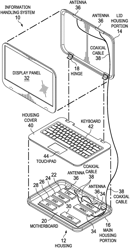
In a recent patent application, Dell Products L. P. has proposed an innovative solution to address the problem of excess thermal energy in electronic devices. The information handling system EMI shield system described in the patent combines the use of a Faraday cage with a surface painted with graphene paint to aid in the dissipation of thermal energy. The EMI shield system comprises a frame that connects to the circuit board and forms a boundary around the electronic device connector. This frame interfaces with ground to enclose the electronic device and prevent electromagnetic interference. Additionally, a separate shield is coupled over the frame to further enclose the electronic device. What sets this system apart is the application of graphene paint on the shield's surface. Graphene, a highly conductive and lightweight material, has shown significant promise in various technological applications. By painting the shield with graphene, Dell aims to enhance the dissipation of excess thermal energy, thereby potentially improving the overall performance and longevity of electronic devices. While the patent application is undoubtedly intriguing, it is important to remember that not all patented inventions become commercial products. Dell faces numerous challenges in translating this concept into a marketable solution. The practicality, cost-effectiveness, and compatibility of a graphene-painted shield with existing electronic devices remain uncertain. Competitor products that already offer thermal management solutions, such as advanced cooling systems or improved heat sinks, would also present a significant hurdle for Dell. Nonetheless, the potential uses for this technology are exciting and could have far-reaching implications for the future of electronic devices, particularly in terms of energy efficiency and device lifespan. As we ponder the future of thermal management in electronic devices, it's essential to consider the practicality and feasibility of integrating a graphene-painted shield into the manufacturing process. Can Dell overcome the challenges and turn this patent into a groundbreaking product? Share your thoughts and insights in the comments below.
The text describes an EMI shield system that is designed to help dissipate excess thermal energy from electronic devices. The system includes a frame that is coupled to the circuit board, and a shield that is separate from the frame and covers the electronic device connector. The shield is painted with graphene paint, which helps reject excess thermal energy from within the shield.
US Patent 11822395
Microsoft Technology Licensing, LLC
Processor-based systems manage power demand with configurable local frequency throttling
What is this invention?
Processor-based system employing configurable local frequency throttling management to manage power demand and consumption, and related methods
A processor-based system was found,
That employed configurable throttling around.
It reduced the frequency when an event came about,
To ensure power supply stayed sound.
The voltage would be too slow, so it chose to throttle instead -
This way the processor could keep ahead!
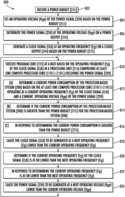
Microsoft Technology Licensing, LLC has recently filed a patent that details a new innovation in processor-based systems called "configurable local frequency throttling management." In simpler terms, this technology aims to effectively manage power demand and consumption in processor-based devices, such as computers and smartphones. At its core, this patent focuses on employing a clock control circuit within the processor. This circuit generates a clock signal at a specified frequency to regulate the processor's operating frequency. In case of unexpected events, the clock control circuit can dynamically throttle, or limit and reduce, the frequency of the clock signal. This technique aims to ensure that the processor can continue functioning under interrupted or reduced power supply conditions. One of the key advantages of this method is that it prioritizes reducing power demand, allowing the processor to remain operational even with restricted power supply. Moreover, it claims to be faster than traditional methods that throttle the operating voltage of power provided to the processor. While this patent showcases a promising advancement in power management for processor-based systems, it is important to note that not all patented inventions end up being integrated into actual products. However, if implemented successfully, this technology could have wide-ranging applications in various devices where power efficiency is crucial. Competing products in the market often employ different strategies to manage power consumption. For example, some devices use advanced sleep modes or dynamic voltage scaling to optimize power usage. This patent introduces an additional approach, specifically focusing on frequency throttling, which could potentially complement existing power management techniques. Considering the increasing demand for energy-efficient technology, it would be intriguing to see how this patent's concept could be translated into practical applications. How do you think such frequency throttling management could impact the power efficiency of future processor-based devices? Share your thoughts in the comments section below.
Processor-based systems employing configurable local frequency throttling management to manage power demand and consumption are described. The clock control circuit is configured to dynamically throttle (i.e., limit and/or reduce) the frequency of a clock signal clocking the processor in response to a frequency throttle event that may be an unexpected event. Reducing power demand may be important to ensure that the processor can continue to operate under interrupted or reduced power supply conditions. It may be faster to throttle the operating frequency of a processor than to throttle the operating voltage of power supplied to the processor.
US Patent 11822414
Microsoft Technology Licensing, LLC
System and Method for Sampling Telemetry Events
What is this invention?
Dynamic remote collection of supplemental diagnostic data and triggering of client actions for client software application
A system and method for sampling,
Telemetry events it was a-mapping.
It monitored the processor's instructions,
And when unique tags had mentions,
It grabbed stack data with some elation!
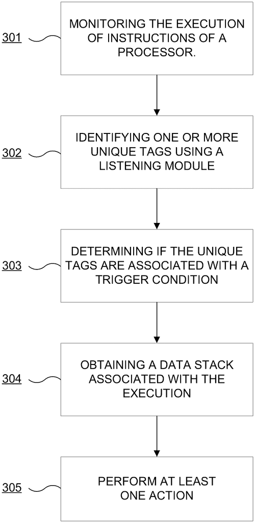
In a recent patent filed by Microsoft Technology Licensing, LLC, a new system and method for sampling telemetry events is described. The invention focuses on monitoring the execution of instructions by a processor and extracting valuable data based on certain trigger conditions. The key feature of this technology lies in its ability to identify unique tags during the monitoring process. These tags serve as markers for specific events or conditions that the system needs to track. By dynamically modifying the trigger conditions remotely, the invention allows for flexible and customizable data collection. Upon identification, the system retrieves a portion of a stack data structure associated with the execution of instructions. This stack data structure encapsulates information about the internal processes and state of the processor, providing valuable insights into the system's behavior and performance. Based on the collected data, the system can then perform various actions. While the patent does not explicitly specify these actions, one can imagine potential uses such as identifying and resolving software bugs, optimizing system performance, or providing real-time analytics during critical operations. The patent does not mention any specific competitors' products, but we can draw parallels to similar technologies already in the market. Companies like Splunk and Datadog offer telemetry and log monitoring solutions, which are widely utilized for application performance management and troubleshooting. As with any patent, it is important to stay grounded in our expectations. While the idea behind this system and method for sampling telemetry events is intriguing, it remains to be seen if it will actually materialize into a tangible product. Patents are often filed to protect ideas and technologies, but not all of them make it past the concept stage. Considering the potential applications and the increasing demand for monitoring and optimizing system performance, it would be interesting to know if readers believe such a technology could find practical implementation. How valuable do you think this system would be in your organization's operations? Let us know in the comments below.
The system and method for sampling telemetry events described herein provides for monitoring execution of instructions by a processor, identifying one or more unique tags associated with the execution of the instructions, and determining if the one or more unique tags is associated with at least one of the one or more trigger conditions. If it is determined that the one or more unique tags is associated with at least one of the one or more trigger conditions, then a portion of a stack data structure associated with the execution of the instructions by the processor can be obtained. The at least one action can be performed based on this determination.
US Patent 11822452
Microsoft Technology Licensing, LLC
Telemetry of Execution Delivers Insight into Program Performance
What is this invention?
Execution-time telemetry reporting using object model
A telemetry process for software,
For subscribers to get reports galore.
The scope is evaluated,
Objects augmented and created;
Reports based on the subscribed-to model they pour!
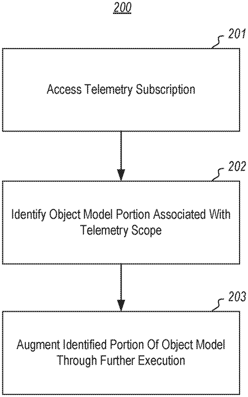
Microsoft Technology Licensing, LLC has recently applied for a patent that could potentially revolutionize the way software programs are monitored and analyzed. The patent, titled "The execution-time reporting of telemetry of execution of a software program," outlines a system where subscribers can submit subscriptions to receive telemetry of a software program's execution. The concept is intriguing - as each subscription is received, the system evaluates the scope of telemetry requested and determines which portion of an object model should be augmented. This augmented portion would include information related to the subscribed telemetry scope. As the computer program is executed, this augmented portion of the object model is updated, and subsequently, telemetry reports are generated based on the defined subscription-specific portion of the object model. On the surface, this technology seems to offer significant potential. Developers and software engineers could gain invaluable insights into how their programs operate in real-time, allowing for quicker identification and resolution of any issues or bugs. By receiving telemetry reports tailored to their specific needs, subscribers could fine-tune their software's performance, leading to improved user experiences. However, it's important to consider the current market landscape. Already, there are several competitor products that offer telemetry and reporting solutions for software programs, allowing developers to gather data on program performance. It remains to be seen whether Microsoft's proposed system would offer enough unique features or advantages to surpass these existing alternatives. Moreover, while the patent application outlines the concept in detail, it's crucial to remember that having a patent does not guarantee that the technology will make it to market. Many patented inventions end up being shelved due to various reasons, such as feasibility constraints or market demand. Nevertheless, the potential applications of this technology are fascinating to ponder. Imagine a world where software programs are continuously optimized based on real-time telemetry data. Bugs could be identified and fixed almost instantaneously, and user experiences could be tailored to individual preferences with great precision. Do you see this kind of telemetry reporting system as a game-changer for software development? Or do you think it's an incremental improvement over existing solutions? Share your thoughts and insights in the comments below.
The text describes the process of telemetry reporting for software execution. Subscribers submit subscriptions to receive reports on the execution of a program. Once a subscription is accepted, the telemetry scope is evaluated to determine which portions of an object model will be augmented. The augmented portions are then added to the object model as it is executed further. Telemetry reports are generated based on this interpretation of the subscribed-to portion of the object model.
US Patent 11822458
Microsoft Technology Licensing, LLC
A Method for Objective Code Branch Verification: Assessing Developer-Specified Pass Conditions
What is this invention?
Executable code branch annotations for objective branch verification
A counter value and pass indicator
Are tracked for each code branch's behavior
It helps assess intent,
To verify that it went
As the author had planned in his favor.
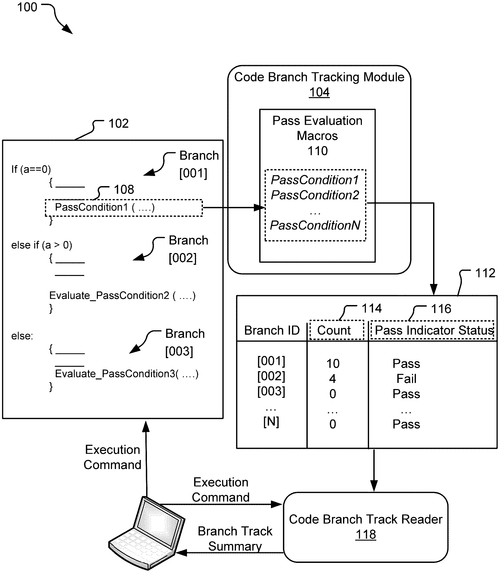
In a recent patent application, Microsoft Technology Licensing, LLC has proposed a method for objective code branch verification. The patent outlines a process that utilizes code branch annotations to assess whether each branch of code is functioning as intended by its author. The method involves maintaining and dynamically updating a counter value and a pass indicator status for each annotated code branch within a code body. The counter value represents the number of times a particular branch has executed, while the pass indicator status indicates whether the pass conditions specified by the developer for that branch have been satisfied or not. While the patent provides a potentially useful tool for developers to verify the functionality of their code, it is important to note that it is just a patent application at this stage, and Microsoft has not yet announced any specific plans to implement this method into a product. That being said, the idea behind this patent could have potential applications in software development, particularly for detecting and debugging code branches that may not be working as intended. By providing developers with a systematic way of assessing code functionality, this method has the potential to streamline the development process and improve software quality. It's worth mentioning that there are existing tools in the market designed to assist developers in code branch verification, such as test-driven development frameworks and code coverage analysis tools. However, Microsoft's proposed method seems to offer a unique approach, leveraging counter values and pass indicators to provide a comprehensive assessment. As with any new technology, the true value of this method will ultimately depend on its practicality and effectiveness when implemented. Will it prove to be a game-changer in the world of software development? Or will it be overshadowed by existing solutions? Only time will tell. What are your thoughts on this proposed method for objective code branch verification? Do you see it as a valuable tool for developers, or do you believe there are already sufficient alternatives available? Share your opinions in the comments below!
The code verification method includes maintaining and dynamically updating both a counter value and a pass indicator status in association with each of multiple annotated code branches defined within a code body during execution of the code body. The counter value for each annotated code branch represents a number of times the annotated code branch has executed within a current run-time environment, and the pass indicator status indicates satisfaction or non-satisfaction of a pass condition identified within the code branch that is determined based on the counter value for the associated code branch. This allows for objective assessment of developer intent when verifying that individualcode branches are functioning as intended by their authors.
US Patent 11822468
Microsoft Technology Licensing, LLC
Heuristics-based concurrent edit detector (“ConE”) helps keep your collaboration on track
What is this invention?
Concurrent edit detection
A program called ConE was created
To help collaborators stay updated
It can detect a conflict
And send out an alert
So that edits will never be heated
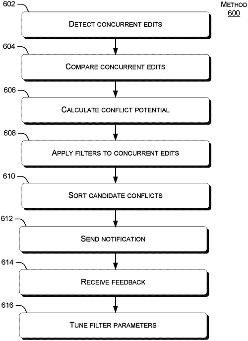
Microsoft Technology Licensing, LLC has filed a patent for a heuristics-based concurrent edit detector called "ConE." This technology aims to notify collaborators about potential conflicts that may arise from edits made by others. In a world where remote work and collaborative platforms have become increasingly important, this invention could have significant implications. ConE works by comparing concurrent edits submitted by collaborators and calculating the extent of overlap between them. It then applies one or more filters to balance recall versus precision, ultimately deciding whether to alert the collaborators about potential conflicts. The patent claims that ConE is light-weight and easily scalable, making it suitable for use in large environments with numerous collaborators. If successfully implemented, ConE could greatly enhance collaboration efficiency. Picture an online document shared among a team of writers, where ConE automatically detects and highlights potential conflicts caused by overlapping edits. This would enable swift resolution and prevent the need for manual cross-checking or redoing work. While this patent showcases an interesting solution, it is important to consider whether it will ever make it into a tangible product. Microsoft faces stiff competition from existing collaboration tools, such as Google Docs and Slack, that are already widely adopted. It remains to be seen if ConE can offer a significant enough advantage to outweigh the inertia associated with transitioning to a new platform. Moreover, the patent description lacks specific details on the underlying technology and the granularity of potential conflicts detected. Without a clear understanding of how ConE works at a technical level, it becomes difficult to evaluate its practical implications accurately. Regardless, the concept behind ConE is intriguing and opens up possibilities for the future of collaborative editing. Do you think a tool like ConE would significantly improve your collaborative work experience? How do you currently navigate potential conflicts when working with others on shared documents? Let us know in the comments below.
ConE is a heuristics-based concurrent edit detector that can notify collaborators about potential conflicts that may be caused by edits made by other collaborators. ConE may compare concurrent edits submitted by collaborators, calculate the extent of overlap between two sets of edits, apply one or more filters to balance recall versus precision, and decide whether to alert the collaborators about candidate potential conflicts. ConE may be light-weight and easily scalable to work in a very large environment with numerous collaborators.
US Patent 11822518