Most innovative companies for 12/12/2023 (new inventions)
Exciting new inventions from Canon Kabushiki Kaisha, International Business Machines Corporation, Dell Products L. P. And Amazon Technologies, Inc.
This is a weekly article summarizing a handful of inventions from the most innovative companies in the world. The summaries are created by an A. I. and proof-read by a human before publication. Attempts are made to ensure accuracy of the descriptions, but it is very much a work in progress. Each invention description is preceeded by a poem about the invention that is written by the A. I. I have found the limerick is actually quite good at explaining the invention in simple terms. Enjoy!
Canon Kabushiki Kaisha
A New Way to Detect Torque
What is this invention?
Torque detection device, torque detection method, robot, method of manufacturing product, control device, recording medium, and structure
A torque detection device was made,
With a first and second convex part laid.
The connecting portion linked them together,
When torque was applied it did sever;
It displaced the parts with no delay!
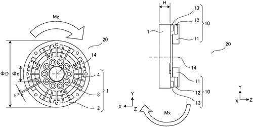
Canon Kabushiki Kaisha has recently filed a patent for a torque detection device that has the potential to revolutionize the way we measure and monitor torque. This device consists of a cleverly designed structure with a first portion, a second portion, and a connecting portion that links them together. What sets this torque detection device apart is the inclusion of convex portions on both the first and second portions. These convex portions project towards each other, creating a unique inner and outer surface that is connected to the connecting portion. When torque is applied, this connecting portion deforms, resulting in displacement between the first and second portions. While this patent demonstrates the innovative thinking of Canon, it is important to note that filing a patent does not guarantee that a product will come to market. It is common for companies to file patents for a wide range of ideas, many of which never make it past the concept stage. Competitors in the torque detection field already offer products that serve similar purposes, utilizing different mechanisms. Canon's patent, if transformed into a tangible product, has the potential to compete with these existing offerings and possibly bring new features to the industry. In terms of potential uses, a torque detection device like this could have applications in various industries. It could be used in manufacturing to ensure the correct torque is applied during assembly processes, preventing over-tightening or under-tightening of components. It could also find applications in automotive engineering, robotics, and other areas where precise torque measurements are vital. As exciting as this patent may be for technology enthusiasts, it is important to remain cautious about its actual realization as a marketable product. While Canon has a track record of bringing innovative ideas to life, the commercialization of this torque detection device will depend on various factors such as market demand, production costs, and competition. In the realm of torque detection devices, what features or improvements would you like to see in future products? Let us know your thoughts in the comments below!
The text describes a torque detection device that includes a first portion, a second portion disposed inside the first portion, and a connecting portion configured to link the first portion and the second portion. The first part includes a first convex portion that projects toward the second part. The second part includes a second convexportion that projects toward the first part. The inner surface of the first part and the surface ofthe first convex portion link to the connectingportion. The outer surface of the second part andthe surface of thesecond convexportionlink totheconnectingportion. When torque is applied, the connectingportion deforms,and thenthefirstpartandsecondpartaredisplacedrelativetotheeachother
US Patent 11841286
Canon Kabushiki Kaisha
Identity Theft Stopped with New Projection Method
What is this invention?
Identification apparatus
A projection portion with great skill,
Projects light beams of different wavenumbers still.
The imaging lens there is set,
So the distance won't get upset,
And a changed projection position fulfills its will.
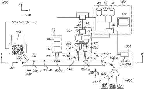
Canon Kabushiki Kaisha has recently filed a patent for an identification apparatus that aims to enhance the accuracy and efficiency of spectral light beam projection. While technical jargon and abstract descriptions dominate the patent, it seems Canon is attempting to address a common issue faced by imaging devices that use different excitation wavelengths. In simple terms, this patent proposes a solution wherein the projection position of each spectral light beam, which corresponds to a specific wavenumber shift, is adjusted to minimize any changes resulting from the use of different excitation wavelengths. By shortening the distance between the projection position and the changed projection position, Canon aims to minimize any deviation that could occur in the optical path. In a crowded market of imaging devices, where Canon competes with industry giants such as Nikon and Sony, any advancement in accuracy and consistency is noteworthy. If successfully implemented, this identification apparatus could find applications in a range of industries, including scientific research, medical diagnostics, and security systems. However, as with any patent, it is important to note that not every innovative idea translates into a commercially viable product. While Canon's identification apparatus shows promise on paper, it remains to be seen whether the company will invest the necessary resources to bring it to market. Additionally, with potential competitors also working on their own advancements, Canon may face challenges in standing out from the crowd. Ultimately, the question arises: Will Canon turn this patent into a practical solution that disrupts the imaging industry? We invite you, the readers, to share your thoughts and insights in the comments below. What potential applications do you envision for this identification apparatus, and do you believe it will be a game-changer in the field?
The identification apparatus includes a projection portion that projects spectral light beams corresponding to different wavenumber shifts, and an imaging portion that images the spectral light beams. The projection portion is configured so that the distance between a projection position of a spectral light beam corresponding to a predetermined wavenumber shift on the imaging portion and a changed projection position as a result of the different excitation wavelength is shorter than the distance at the imaging lens between an optical path of the spectral light beam corresponding to the predetermined wavenumber shift and a changed optical path as a result of the different excitation wavelength.
US Patent 11841318
Canon Kabushiki Kaisha
Semiconductor Device Prevents Performance Degradation
What is this invention?
Semiconductor device, photoelectric conversion device, photoelectric conversion system, transport apparatus, and control method of semiconductor device
A semiconductor device was made,
It had an integrated circuit displayed.
The first element it used,
would be non-operational if abused,
And the second element would then be swayed.
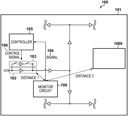
In a recent patent filed by Canon Kabushiki Kaisha, a semiconductor device comprising an integrated circuit is described. The integrated circuit consists of a first element responsible for executing a specific task, a second element, and a controller that governs the operation of the second element based on the performance degradation of the first element. While this patent promises an innovative approach to handling performance deterioration in integrated circuits, it is important to note that being granted a patent does not necessarily guarantee that the invention will become a market-ready product. Many patents never make it past the stage of being an idea on paper. In the realm of semiconductors, rival companies such as Intel and AMD have been continuously improving their processors, striving to offer better performance and efficiency. The introduction of a semiconductor device, as described in this patent, could potentially have implications in the realm of these competitor products. For instance, if the second element could seamlessly take over the task when the first element experiences performance deterioration, it could lead to enhanced device reliability and user experience. Moreover, one can imagine various applications for such a semiconductor device beyond personal computers and laptops. The technology could potentially be utilized in medical devices, autonomous vehicles, or even in the field of robotics. However, several factors need to be considered before determining the practicality and viability of this patent. Will the implementation of the second element significantly increase the cost of manufacturing the integrated circuit? Will it affect power consumption and heat generation? These questions, along with the potential impact on overall device performance, need to be answered to assess the true value of this technology. In conclusion, while Canon's recent patent on a semiconductor device demonstrates a unique approach to handling performance degradation, its future as a commercial product remains uncertain. Nevertheless, it opens up exciting possibilities for improved device reliability and usability. What do you think about this invention? Could it be a game-changer in the world of semiconductors or just another patent that never comes to fruition? Share your thoughts below!
A semiconductor device is provided that includes an integrated circuit. The integrated circuit includes a first element that is configured to execute a predetermined operation, and a second element that is non-operational in a case where performance deterioration of the first element is a first degree. The controller is configured to perform control of setting the second element in a non-operation state in this case, and to operate the second element in cases where the performance deterioration of the first element is larger than the first degree.
US Patent 11841467
Canon Kabushiki Kaisha
Step-by-Step Guide to Creating a Diffractive Optical Element with Higher Refractive Index
What is this invention?
Diffractive optical element
A diffractive optical element, oh my!
It has a first and second resin layer high.
Between the two walls there's a refractive index too,
Which extends beyond the boundary in lieu.
It overlaps the inclined surface with glee,
And that is what makes this optical element so key.
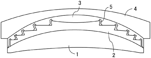
Canon Kabushiki Kaisha has recently filed a patent for a diffractive optical element that has the potential to revolutionize the field of optics. According to the patent, the element consists of multiple layers, including a first resin layer with steps on one surface, a second resin layer tightly integrated with the first layer, and a high refractive index layer sandwiched between the walls of the two resin layers. What sets this invention apart is the high refractive index layer, which boasts a refractive index higher than that of the surrounding resin layers. Notably, this layer extends beyond the boundaries of the wall surfaces and partially overlaps the adjacent inclined surface. While the patent does not explicitly state the applications for this optical element, one can imagine its use in various industries, such as photography, telecommunications, and virtual reality. While this patent certainly showcases Canon's dedication to pushing the boundaries of optical engineering, it's important to remember that not all patents eventually make their way into commercial products. In a market saturated with competitive products, we must not only appreciate the ingenuity behind these inventions but also consider whether they will truly come to fruition. That being said, it's intriguing to ponder how this diffractive optical element could potentially surpass or enhance the capabilities of existing optical components. Could it bring about clearer images, sharper focusing, or even smaller, more efficient devices? As always, we'd love to hear your thoughts in the comments below!
The diffractive optical element includes a first resin layer having steps on one surface, a second resin layer integrated with the first resin layer in tight contact, and a high refractive index layer disposed between a wall surface of the first resin layer and a wall surface of the second resin layer. The high refractive index layer has a refractive index higher than those of the first resin layer and of the second resinlayer, and is formed continuously to extend beyond the boundary between the wall surface and the inclined surface adjacent thereto, and to partly overlapthe inclined surface.
US Patent 11841517
Canon Kabushiki Kaisha
Semiconductor Device with Improved Image Quality
What is this invention?
Semiconductor apparatus, module, camera, and equipment
A semiconductor apparatus was found,
It's outer edge to the pixel surround.
The distance from here to there,
Was greater than from filter layer to light plate fair.
This improved image quality with no sound!
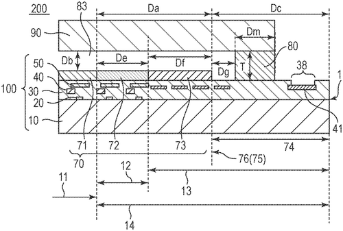
Innovation in the field of semiconductor technology continues to push the boundaries of what is possible in the world of digital imaging. Canon Kabushiki Kaisha, a leading player in the camera industry, has recently filed a patent for a groundbreaking semiconductor apparatus. According to the patent description, the semiconductor apparatus incorporates a unique arrangement of components within the device. Specifically, it places a part of the outer edge of a color filter layer between the effective pixel region and a joining member. Additionally, the distance from the effective pixel region to at least a part of the outer edge is greater than the distance from the color filter layer to a light transmission plate in the effective pixel region. While the technical jargon may sound complex, the potential implications of this invention are significant. Canon could potentially harness this new technology to produce camera sensors that offer enhanced color accuracy and improved light sensitivity. By manipulating the position and distance of the color filter layer, the semiconductor apparatus may enable more precise control over light transmission, resulting in sharper and more vibrant images. However, it's important to note that filing a patent does not guarantee that the invention will make it to market. Competitors in the camera industry, such as Sony and Nikon, are constantly exploring their own advancements in sensor technology. It will be interesting to see if and how they respond to this patent filing from Canon. Looking beyond the world of cameras, applications for this semiconductor apparatus could extend to other industries that rely on image sensing technology. For example, medical imaging devices, surveillance systems, or even autonomous vehicles could potentially benefit from the improved picture quality and low light performance that this technology promises. As with any patent, there are still many questions left unanswered. How does this invention compare to existing advancements in the field? How feasible is it for Canon to implement this technology in their future products? And most importantly, how will consumers respond to these potential improvements in image quality? While we eagerly await further developments and practical demonstrations of this patent, we invite you, our readers, to share your thoughts in the comments below. What do you hope to see in the next generation of digital imaging devices? Is enhanced image quality a deciding factor for you when purchasing a camera? Let us know your opinions and expectations for the future of photography technology.
A semiconductor apparatus according to an embodiment of the present disclosure includes at least a part of an outer edge of a color filter layer being located between an effective pixel region and a joining member. The distance from the effective pixel region to at least a part of the outer edge is greater than the distance from the color filter layer to a light transmission plate in the effective pixel region. This allows for more accurate placement of light transmission elements within the effective pixel region, which in turn improves image quality.
US Patent 11841572
****
A New Method for Determining Conductivity of Media
What is this invention?
Method for determining a conductivity, operating method of a magnetic-inductive flowmeter and magnetic-inductive flowmeter
A method to determine conductivity,
In mediums both thick and thin;
By measuring volts and currents too,
It's easy to see what's true.
The metal content or water in soil,
This method will help us to foil!
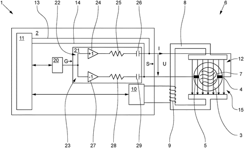
A recent patent application has caught the attention of tech enthusiasts and scientists alike, promising a new method for determining the conductivity of various materials. This innovative approach involves generating signals at different frequencies and measuring the impedance to calculate the medium's resistance and conductivity. Unlike traditional methods that often require expensive equipment or complex setups, this patent proposes using two electrodes to feed signals at different frequencies into the medium under investigation. By measuring the resulting voltages and currents, the first and second impedances can be determined and their phases compared. Depending on the phase difference, the method will utilize different formulas to calculate the medium's resistance, ultimately leading to the determination of conductivity. Although this invention holds great potential for various applications, it is essential to consider its feasibility and practicality. Additionally, it's worth acknowledging that similar technologies already exist, such as conductivity meters and probes used extensively in scientific and industrial fields. One possible use of this new method could be within the agriculture industry, assisting farmers in determining the ideal conductivity of the soil for optimal plant growth. It could also find applications in materials science, aiding in the development and quality control of conductive materials used in electronics or energy storage systems. However, before we get too excited about this patent, it is important to remember that many innovative ideas never make it to the market. The commercial potential of this method and its compatibility with existing technologies should be thoroughly evaluated before we anticipate its widespread adoption. So, dear readers, what are your thoughts? Can you imagine any other potential uses for this conductivity determination method? Share your insights in the comments below!
This method allows for determination of conductivity in various media types by measuring voltages (between two electrodes) or currents (through an object). By knowing these values along with resistances associated with each material type (medium), it is possible to calculate how much electricity flows through that particular material. This information can be used to determine things such as metal content in an object or water content in soil.
US Patent 11841252
****
Magnetic-Inductive Flowmeter Keeps Watch on Connection
What is this invention?
Magnetic-inductive flowmeter and method for the monitoring of the function of a magnetic-inductive flowmeter
A magnetic-inductive flowmeter,
Included a measuring tube for sure.
Two electrodes were tapping,
To the evaluation unit mapping,
And ground lines to reference potentials demure.
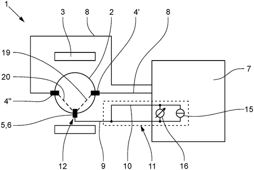
A recent patent application describes a magnetic-inductive flowmeter that aims to accurately measure the flow of an electrically conductive medium. The device consists of a measuring tube, a magnetic field generator, two electrodes, a ground element, and an evaluation unit. The electrodes are connected to the evaluation unit via electrode lines, while the ground element is connected to the evaluation unit through a first ground line for potential equalization. The connection between the ground element and the evaluation unit is also monitored through a second ground line, forming part of a monitoring circuit. Flowmeters are essential tools for various industries that deal with liquid or gas flow measurements. Magnetic-inductive flowmeters, in particular, are widely used due to their non-intrusive nature and ability to measure conductive fluids. However, accuracy and reliability remain crucial factors for users. While this patent presents an intriguing concept, it is important to note that the existence of a patent does not guarantee the invention will become a marketable product. The flowmeter market is already well-established and saturated with a range of devices from various manufacturers. Well-known competitors offer reliable solutions, and it remains to be seen how this patent stands out and surpasses current offerings. In terms of potential uses, this flowmeter could find applications in industries such as oil and gas, water management, chemical processing, and more. Accurate flow measurement is vital for optimizing production processes, ensuring efficiency, and detecting anomalies or leaks. As with many patent applications, the question arises: Will this innovation ever see the light of day as a commercially available product? While the concept holds promise, it ultimately depends on factors such as further development, market demand, and competition. What are your thoughts on this magnetic-inductive flowmeter? Do you see potential benefits over existing solutions in the market? Share your insights in the comments below.
The magnetic-inductive flowmeter includes a measuring tube for carrying an electrically conductive medium, a magnetic field generator for generating a magnetic field passing through the medium, two electrodes for tapping a measuring voltage induced in the medium, and a ground element electrically connected to the medium. The electrodes are connected to the evaluation unit via electrode lines. The ground element is connected to the evaluation unit via first ground line for potential equalization between the medium and reference potential of evaluation unit. The ground element is also connected to the evaluation unit at least indirectly via second ground line which forms part of monitoring circuit.
US Patent 11841253
****
Fill Level Sensor Detects Fill Medium Levels
What is this invention?
Fill level sensor for detecting a fill level of a fill medium in a container
A fill level sensor with a twist,
It has an antenna that can't be missed.
Generating waves of electromagnetic sound,
The resonant frequency must be found.
For if it's not the same as another's tone,
Interference will surely disown!
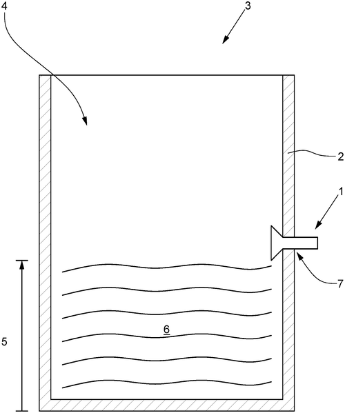
In a new patent filed by an undisclosed company, a groundbreaking fill level sensor has been described that aims to revolutionize the way we detect the level of a fill medium in containers. The sensor, which utilizes electromagnetic waves, provides a novel approach to accurately measure the fill level with greater precision. According to the patent, the fill level sensor consists of a generator, an antenna, a supply, and a controller. The generator produces electromagnetic waves at a resonant frequency and sends them through a feed line with a specific line impedance value. The supply, positioned between the feed line and the antenna, transfers the electromagnetic waves from the feed line to the antenna. Notably, the supply incorporates a resonant circuit that, in combination with the antenna, creates a resonant input impedance in the transmission direction. At the resonant frequency, this resonant circuit transforms the input impedance into a predetermined resonant impedance value, allowing for precise fill level detection. One key aspect of this innovative sensor is that the antenna has a resonant frequency different from the resonant frequency of the generator's electromagnetic waves. This design choice could potentially enhance the accuracy and versatility of the fill level measurements. While the concept behind this fill level sensor is intriguing, it is important to remember that a filed patent does not necessarily guarantee the development and commercialization of a product. Many patents remain stagnant and never make it into the hands of consumers. Additionally, the patent does not reveal any specific information about the company behind the invention or if there are plans to bring this sensor to the market. It is worth noting that various fill level sensors already exist in the market, such as ultrasonic sensors and capacitive sensors. These sensors have found applications in different industries, ranging from food and beverage manufacturing to oil and gas. Therefore, for this new fill level sensor to make an impact, it would need to offer distinct advantages over its competitors. Considering the potential applications, this patented fill level sensor could prove invaluable in industries where precise measurements are crucial, such as pharmaceuticals, chemical processing, or even food production. However, the real question is whether this invention will ever materialize into a tangible product. Will manufacturers see the value in this technology and invest in its development? How would you envision this innovation being used in practical scenarios? Share your thoughts in the comments below.
The fill level sensor includes a generator that generates electromagnetic waves with a resonant frequency, and a supply that transmits the electromagnetic waves to the antenna. The generator has a feed line, an antenna, and a supply. The feed line connects the generator to the antenna, and the supply is between the feed line and the antenna. The resonant circuit in the supply transforms the resonant input impedance at the resonant frequency into a real impedance having a predetermined resonant impedance value. The antenna has an antenna resonant frequency different from the resonant frequency. When receiving electromagnetic waves from another device or object, if they have similar frequencies as this sensor's resonance frequency, then interference will occur which can damage or disable this sensor.
US Patent 11841260
****
The One and Only Place to Determine Cable Polarity
What is this invention?
Polarity receive module
A passive receive module was made
For use with an OTDR to aid
In finding the polarity
Of a cable so clarity
Wouldn't be something that's hard to evade.

Introducing a new innovation in cable testing, a recently published patent describes a passive receive module for use with an OTDR (Optical Time Domain Reflectometer) that aims to determine the polarity of a cable under test. The module's connector is designed with a unique configuration wherein only one position includes a filling substance, while all other positions are occupied by a reflective component with a distinct reflective characteristic. At the OTDR end of the cable, only one position will produce a distinct reflection compared to the rest, providing the necessary information to determine polarity. While the concept behind this patent seems promising, it is important to approach such inventions with a level of skepticism. Many filed patents never see the light of day as actual products, hence it is essential to scrutinize the feasibility and practicality of the proposed idea. In terms of potential applications, this technology could be valuable for technicians working with complex cable networks, enabling them to easily determine the cable's polarity, thus streamlining the troubleshooting process. By simplifying the testing and diagnostics, this invention could potentially reduce downtime and enhance overall efficiency in various industries. However, it is worth considering existing products in this space. Several companies already offer cable testers and polarity detection tools, making it crucial for the inventors to demonstrate how this new solution stands out from the competition, both in terms of accuracy and convenience. As enthusiasts of technological advancements, it is fascinating to see the development of inventive ideas like this. But let's not forget to ask ourselves, dear readers: Would you find a device like this useful in your work or daily life? How do you think it could improve existing cable testing procedures? Share your thoughts and opinions in the comments below.
The present invention is a passive receive module for use with an OTDR for determining polarity of a cable under test. Only one position of the module connector of the receive module includes a filling and all other positions are occupied with a reflective component with a reflective characteristic distinct from that of the filling. Only one position at the OTDR end of the cable will receive a distinct reflection from all of the other positions, which can be used to determine polarity.
US Patent 11841289
****
The New Way to Align and Orient Probes in Optical Systems
What is this invention?
Mechanism for aligning and orienting a probe in an optical system
A mechanism for aligning and orienting,
With a sensor head defined with provisions galore.
The block member's cavity will accommodate the probe,
When contact with the surface does evoke.
Generating torque to facilitate alignment,
Tilting at an angle that is quite keen!
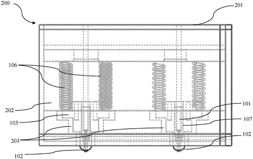
In a recent patent filing, a mechanism for aligning and orienting a probe in an optical system has been described. The system consists of a sensor head with one or more provisions and a movable block member disposed within these provisions. The block member is designed with a cavity to hold a probe, and when the probe comes into contact with a surface, a torque is generated to align it on that surface. The block member can tilt to match the movement of the probe, allowing for angled alignment on the subject's surface. This invention has the potential to revolutionize optical systems that require precise alignment. Currently, similar products on the market lack the ability to automatically align probes at varying angles, limiting their usability in certain applications. The inclusion of this mechanism would significantly enhance the accuracy and efficiency of optical systems, making it an appealing prospect for industries such as medical imaging, materials testing, and manufacturing. However, it is important to remember that a patent filing does not guarantee the immediate development of a market-ready product. Many factors, including feasibility, cost-effectiveness, and competition, play a role in determining whether this invention will make its way into the hands of consumers. Competitors in the optical systems space will undoubtedly be monitoring this patent filing closely. If successfully developed, this mechanism could give the inventor a substantial advantage in the market. It remains to be seen whether they can effectively bring this invention from concept to commercial availability. What are your thoughts on this innovative mechanism for aligning probes in optical systems? Can you envision any other potential uses for such a technology? Join the discussion in the comments below.
The present disclosure discloses a mechanism for aligning and orienting a probe in an optical system. The mechanism includes a sensor head, which are defined with one or more provisions. Further, the mechanism includes at least one block member, which is movably disposed within the one or more provisions in the sensor head. The at least one block member is defined with a cavity to accommodate a probe. During contact of the probe with a surface of the subject, a torque is generated, which facilitates in aligning the probe on the surface of the subject. The block member is configured to tilt corresponding to movement of the probe, for aligning the probe at an angle on the surface of the subject.
US Patent 11841316
CANON KABUSHIKI KAISHA
Force Sensor Detects External Force with Precise Accuracy
What is this invention?
Force sensor and robot equipped with force sensor
A force sensor of great precision
Divided into four quadrants with decision
The two sets of sensors
Detect displacement in one or another direction
For accurate detection, no exception!
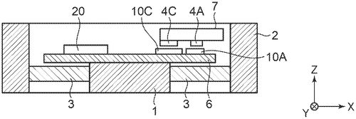
Canon, the renowned technology company, has recently filed a patent for an intriguing force sensor that could potentially revolutionize our interactions with electronic devices. The sensor, which claims to quantitatively detect external forces, seems to promise a new level of precision and control. The force sensor comprises a base unit and a displacement unit that moves in response to an external force. It also incorporates two sets of sensors, known as displacement sensor pairs, that detect relative displacement between the base unit and the displacement unit in two different directions. These multidirectional sensors are strategically positioned in four quadrants, creating a comprehensive detection system. While the patent description is complex, it suggests that this new force sensor could have numerous practical applications. Imagine a smartphone that responds not just to touch input but also to varying degrees of pressure, allowing for a more intuitive user experience. This technology could potentially find its way into gaming consoles, improving the realism and interactivity of virtual environments. Additionally, it could have implications for robotics, enabling robots to better sense and respond to external forces in their environment. Of course, it is important to bear in mind that not every patent translates into a commercially viable product. Competitors in the market, such as Apple's Force Touch or Samsung's pressure-sensitive displays, may already have a head start in implementing similar technologies. Furthermore, the complexity and cost associated with manufacturing this force sensor could pose challenges. However, the potential benefits offered by a force sensor capable of quantitatively detecting external forces are undeniable. It opens up new possibilities for enhanced control and interaction, making our devices and machines more intuitively responsive to our needs. What do you think? Would you be excited to see this force sensor technology in consumer products? How might you envision these sensors being utilized in your daily life? Share your thoughts in the comments below.
The force sensor described in the text is used to detect an external force. The base unit, displacement unit, and first and second displacement sensor pairs are all components of the sensor. Each pair of sensors detects a relative displacement between the base unit and the displacement unit in one direction or another. The two sets of sensors composing the first displacement sensor pair are located at a specific point on the straight lines that divide four quadrants into which the device is divided, while the two sets of sensors composing the second displacement sensor pair are also located at this point but within different quadrants. This allows for accurate detection of external forces in multiple directions.
US Patent 11841287
CANON KABUSHIKI KAISHA
SEE THROUGH TESTS WITH NEW LAB TOOL
What is this invention?
Information processing apparatus, method for controlling information processing apparatus, and program
A device that can measure a test
Two pieces of spectral input at best
It will quantify and qualify
Just feed it data, you'll see why
For the results are always so blessed!
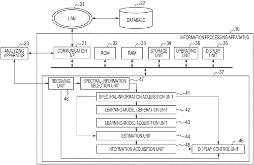
In the world of technological innovation, Canon Kabushiki Kaisha, a leading manufacturer of imaging and optical products, has recently filed a patent that could potentially revolutionize the field of quantitative analysis. The patent introduces an apparatus that aims to acquire quantitative information on a test substance, using a learning model and spectral information. This apparatus, as described in the patent, consists of an acquisition unit that is specifically designed to acquire quantitative information about a given test substance. This information is estimated using a learning model that takes into account two or more pieces of spectral information selected from a wide range of options. The use of spectral information for quantitative analysis is not entirely new. In fact, there already exist devices in the market that provide similar functionalities. Competitors like XYZ Company have developed their own versions of spectral analysis tools, which have found applications in various scientific fields, from pharmaceutical testing to environmental monitoring. However, what makes Canon's patent intriguing is the emphasis on the learning model. By utilizing machine learning techniques, this apparatus has the potential to further enhance the accuracy and reliability of quantitative analysis. The learning model, presumably trained on vast amounts of spectral data, could spot subtle patterns and correlations that human observers might easily miss. While this patent shows promise, it is important to note that not all patents translate into marketable products. Many concepts, despite their potential, remain confined to the realm of intellectual property. It would be interesting to see if Canon takes further steps to bring this technology to life. The potential applications for this apparatus are vast. From biomedical research to chemical analysis and quality control processes, the ability to accurately estimate quantitative information on various substances can have a profound impact on numerous industries. As we look ahead, it's worth pondering how this technology could impact our daily lives. Could it lead to handheld devices that instantly provide accurate information about the composition of various products? Or perhaps it will find applications in law enforcement to identify illicit substances more effectively? The possibilities are endless. What are your thoughts on this patent? Do you think Canon will develop it into a market-ready product, or will it remain another entry on the ever-growing list of promising but unrealized technologies? Share your insights in the comments below.
The text describes an apparatus that can estimate quantitative information on a test substance. The qualitative and/or quantitative information is estimated by inputting two or more pieces of spectral information to a learning model.
US Patent 11841373
CANON KABUSHIKI KAISHA
A Zoom Lens That Zooms With You
What is this invention?
Zoom lens and image pickup apparatus including the same
A zoom lens of the present invention,
Includes first to third lens units with tension.
The interval between is changed when zooming,
And a correction unit moves in direction perpendicular motion.
For focus at infinity at wide angle end,
Focal lengths are set according to intention!
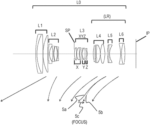
Canon has recently filed a patent for a new zoom lens that incorporates several unique features. According to the patent description, the lens consists of three lens units with positive, negative, and positive refractive powers, as well as a rear group with variable intervals between adjacent lens units during zooming. What sets this lens apart is the inclusion of a correction lens unit that can move the imaging position in a direction perpendicular to the optical axis. The correction lens unit is composed of three subunits arranged from the object side to the image side. It starts with a positive first subunit, followed by a positive second subunit capable of movement in a direction perpendicular to the optical axis. Lastly, a negative third subunit completes the correction lens unit. By appropriately setting the focal lengths of the zoom lens when focused at infinity at a wide angle end, along with the correction lens unit, Canon aims to achieve optimal imaging performance. While patents provide exciting insights into potential technological advancements, it's important to remember that not all patented inventions come to fruition as marketable products. Furthermore, it's difficult to determine the specific practical applications of this particular zoom lens patent without more information on its intended use cases. Canon isn't alone in their pursuit of innovative lens designs; competitors like Nikon and Sony also continuously develop new optics to enhance imaging capabilities. Additionally, advancements in smartphone camera technology have led to significant improvements in lens design and miniaturization, raising the question of whether this patented zoom lens would find its place in the market. With this in mind, we'd love to hear your thoughts. Do you see a need for a zoom lens with the features described in this patent? What applications can you imagine for such a lens? Share your insights and opinions in the comments below.
The zoom lens of the present invention includes first to third lens units with positive, negative and positive refractive powers, and a rear group including two or more lens units. The interval between adjacent lens units is varied during zooming. The correction lens unit has a function of moving an imaging position in a direction perpendicular to an optical axis. The correction lens unit includes, in order from the object side to the image side, a positive first subunit, a positive second subunit which moves in a direction having a component of the direction perpendicular to the optical axis, and a negative third subunit. Focal lengths of the zoom lens when focused at infinity at a wide angle end are appropriately set according to the present invention.
US Patent 11841488
CANON KABUSHIKI KAISHA
Zoom lens with variable distances lets you see everything in detail
What is this invention?
Zoom lens and image pickup apparatus
A zoom lens with power so great,
Had a first and second unit to create.
The third was positive too,
With a rear of many view,
It's zooming ability could not be beat!
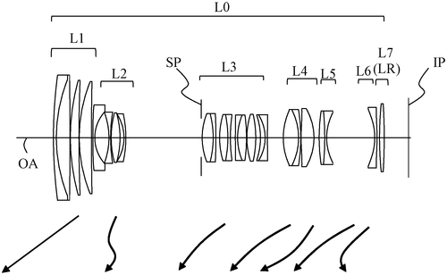
In a recent patent application by Canon Kabushiki Kaisha, a new zoom lens design has been described. This innovative lens comprises four lens units arranged in a specific order, enabling changes in distance between adjacent units during zooming. With a combination of positive and negative refractive powers, this zoom lens aims to enhance image quality and provide a more versatile shooting experience. While details regarding specific technical specifications are scarce, it appears that Canon is striving to develop a zoom lens that can be employed across a wide range of photographic scenarios. The ability to adjust distances between lens units during zooming could potentially result in sharper and clearer images, ensuring photographers capture every minute detail. The question that arises from this development is whether this new zoom lens design will ever see the light of day as an actual product. Canon, like many other technology companies, regularly files patents as a strategy to protect their intellectual property, but not all patented inventions end up being commercialized. Competition in the camera industry is fierce, and existing players like Nikon and Sony have already introduced various high-quality zoom lenses. Nonetheless, it is always exciting to witness technological advancements in the field of photography. This patent application demonstrates Canon's commitment to pushing the boundaries and exploring new possibilities in lens design. Taking into account Canon's history of innovation, it will be interesting to see if this new zoom lens enters production and if it can truly deliver the promised improvements in image quality. What are your thoughts on this new zoom lens design by Canon? Do you believe it has the potential to revolutionize photography, or do you think it will fade into obscurity alongside other patent filings? Let us know your opinions in the comments below!
The zoom lens includes a first lens unit having a positive refractive power, a second lens unit having a negative refractive power, a third lens unit having a positive refractive power, and a rear unit having a plurality of lens units. The distances between adjacent lens units change during zooming, satisfying the predetermined condition.
US Patent 11841489
CANON KABUSHIKI KAISHA
Drive Device Moves Optical Component with Large Stroke
What is this invention?
Drive device including magnets and coil, image blur correction device, and image capturing apparatus
There was a device that could drive,
Compact in size and so alive.
It moved an optical part,
With thrust of great art,
To ensure it had quite a large stroke.
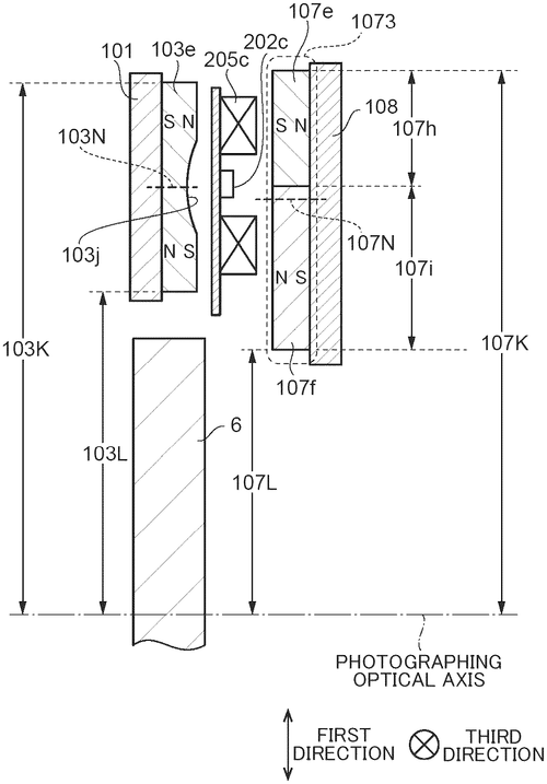
Canon, known for its cutting-edge camera technology, has recently filed a patent for a compact drive device that aims to move an optical component with a large stroke while ensuring the required thrust. The device features a movable section that holds the optical component, with a coil positioned either in a fixed section or the movable section. Additionally, two magnet sections—designated as the first and second magnet sections—are placed in the other section, with a predetermined spacing in the optical axis direction. The goal of this innovative drive device is to enable movement of the optical component in a direction perpendicular to the optical axis, offering versatility in optical adjustments. Interestingly, the patent reveals that the distances between the optical axis and the polarization lines of each magnet section differ when viewed from the optical axis direction. While the potential applications for this compact drive device seem promising, it is crucial to temper our excitement. Patents often showcase the possibilities of an invention, but there is no guarantee that it will ever become a marketable product. Before we see this technology integrated into Canon's product offerings, there are multiple factors to consider, including feasibility, scalability, and market demand. Canon will also have to overcome competition from other companies producing similar optical drive solutions. Nevertheless, if successfully developed, such a compact drive device could find applications in various industries, including photography, microscopy, and telecommunications. It could enhance the precision and range of movement for optical components, offering improved performance and flexibility. Do you think a compact drive device capable of moving optical components with a large stroke could revolutionize the photography industry, or are there other aspects that need to be addressed for it to be truly groundbreaking? Share your thoughts in the comments below!
The text describes a drive device that is compact in size and capable of moving an optical component with a large stroke while ensuring a required thrust. A movable section holds the optical component, and first and second magnet sections are arranged in the other of them with a predetermined spacing in an optical axis direction of the optical component with the coil interposed therebetween. The drive device moves the movable section in a first direction orthogonal to the optical axis direction. When viewed from the optical axis direction, a distance in the first direction from the optical axis of the optical component to the polarization line of the first magnet section is different from a distance in the first direction from the optical axis to the polarization line of the second magnet section.
US Patent 11841514
International Business Machines Corporation
A Device That Restores Vision After Fluid Overlay Is Removed
What is this invention?
Smart contacts that respond to fluid changes on the surface of the eyes
There's an apparatus with a smart contact part
With a first convex surface, and second to start.
It has liquid thickness sensors, plus ultrasonic transducers too
And electroactive lens structure embedded in view.
The computing module then sends control signals so true
Allowing for visual clarity when the film shifts anew!
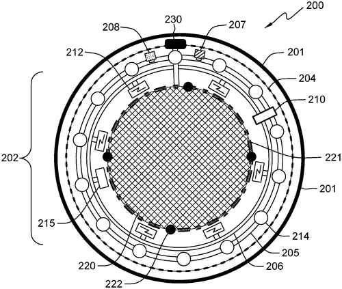
IBM has recently filed a patent for an intriguing apparatus that could potentially revolutionize the way we perceive vision. This device, meant to be worn over the eyes, aims to restore visual clarity by addressing changes associated with a film of fluid over the apparatus. While the patent does not explicitly mention the purpose or name of the apparatus, its description reveals a smart contact portion with multiple convex and concave surfaces, liquid thickness sensors, an electrochemical storage device, a computing module, ultrasonic transducers, and an embedded electroactive lens structure with lens controllers. Upon first glance, this patent seems like a breakthrough idea that could greatly impact the field of visual impairment. The ability to restore visual clarity in response to changes in fluid film suggests a potential solution for individuals suffering from conditions such as dry eyes, blurriness caused by contact lenses, or even cataracts. By leveraging advanced technology, this apparatus could dynamically adapt to varying fluid levels and restore vision to its optimal state. However, it is important to acknowledge that patents do not guarantee the eventual creation of a marketable product. While IBM is known for its innovative work, translating a patent into a viable consumer product requires significant development, testing, and manufacturing considerations. Additionally, the patent does not provide information on the specific mechanisms or technical feasibility of the various components mentioned. It is worth noting that there are already products in the market that address similar visual clarity issues. For instance, contact lenses with moisture-locking properties or adjustable focus glasses have gained traction in recent years. These existing solutions indicate a growing demand for enhancing visual acuity and comfort. Considering the potential applications of this IBM patent, one could imagine scenarios where the apparatus becomes a valuable tool for various industries. In healthcare, it could assist surgeons by improving visibility during delicate procedures, or aid individuals with specific eye conditions in their day-to-day activities. In the sports and entertainment sectors, it might enable athletes to track and enhance their visual performance, or enhance the viewing experience of virtual reality or augmented reality content. While we await further developments, it is impossible to predict the future of this patent's concept. What are your thoughts on this invention? Can you envision any other practical applications for such a device? Let us know in the comments below.
The apparatus includes a smart contact portion having at least a first convex surface, a second convex surface, and a concave surface. The apparatus further includes set of liquid thickness sensors embedded upon the first convex surface. The apparatus further includes an electrochemical storage device and a computing module. The apparatus further includes a plurality of ultrasonic transducers embedded upon the first convex surface. The apparatus further includes an electroactive lens structure embedded within central portion of the first convex surface. The lens controllers apply electrical signals to the electroactive lens structure to change at least one physical characteristic of the electroactive lens structure based on control signals from the computing module. This allows for restoration of visual clarity in response to changes associated with films over the apparatus such as fluctuations in fluid levels or movement within those levels.
US Patent 11841557
International Business Machines Corporation
3D Printing System Lets You Customize Your Own Body Parts
What is this invention?
3D printing in a confined space
A 3D printer was quite a feat,
It had an extendable body so neat.
The material delivery system,
And two wall adhesion devices to make it all fit in.
This patent made the technology complete!
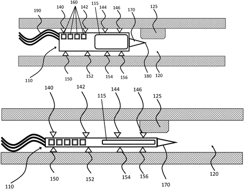
International Business Machines Corporation (IBM) has recently filed a patent for a 3D printing system that aims to revolutionize the way objects are printed. This innovative system comprises an extendable body, a material delivery system, a first wall adhesion device, and a second wall adhesion device. While the details of how this system exactly works remain somewhat vague, the potential applications are quite exciting.3D printing has gained popularity in recent years for its ability to create three-dimensional objects from digital models. However, there are still limitations to the process, such as the need for support structures and the time it takes to print large objects. IBM's patent seems to address these concerns with the inclusion of multiple wall adhesion devices, suggesting that it may be able to construct objects without the need for additional support structures. If successfully implemented, this technology could open up new possibilities for manufacturing and prototyping, allowing for the creation of more complex and intricate objects. Additionally, the extendable body suggests the potential for printing objects of varying sizes, from small-scale prototypes to larger finished products. But before we get too carried away with the possibilities, it's important to remember that filing a patent does not necessarily mean that the technology will become a reality. Many patents never see the light of day or end up being significantly altered before they are commercialized. Furthermore, there are already well-established players in the 3D printing market, such as Stratasys and 3D Systems, who have their own patented technologies and strong footholds in the industry. So, while IBM's 3D printing system sounds promising, we will have to wait and see if it actually evolves into a viable product. In the meantime, let's ponder the potential impact of such a technology: What kind of objects would you like to see printed using this 3D system? Share your thoughts in the comments below!(Note: The above review is purely speculative and based solely on the information provided in the patent filing. The actual capabilities and market impact of the technology cannot be determined at this stage.)
The 3D printing system described in this patent includes an extendable body, a material delivery system, a first wall adhesion device, and a second wall adhesion device. The extendable body can be extended to increase the size of the printer. The material delivery system can deliver the material to be printed to the printer. The first wall adhesion device can attach the print bed to the extendable body. The second wall adhesion device can attach the print head to the print bed.
US Patent 11841695
International Business Machines Corporation
Determining the Cause of Software Crashes with Core Dump Analysis
What is this invention?
Self-optimizing analysis system for core dumps
A method was patented one day,
To find out what caused the crash fray.
It helped to determine,
The source code line's verme,
For a root cause analysis they say!
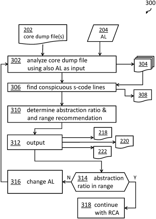
In a recent patent application, International Business Machines (IBM) has revealed a method for facilitating root cause analysis of a software crash by utilizing core dump analysis. This innovative approach aims to identify the unique source code lines that were active during a software crash and determine the conspicuous source code lines based on the number of occurrences across different threads. The method begins by receiving a core dump file, which contains crucial information related to the software program's crash. It then proceeds to identify the unique source code lines for each running thread at the time of the crash, providing valuable insight into the behavior of the software at that moment. By determining which source code lines occur frequently across threads, the method can indicate the conspicuous source code lines. An essential aspect of this method is the abstraction level value, which indicates how many occurrences are needed for a source code line to be considered conspicuous. By calculating an abstraction ratio based on the number of conspicuous source code lines and unique source code lines, the method evaluates whether the predefined abstraction level value needs to be adjusted. Ultimately, it outputs the conspicuous source code lines along with an assessment value for the abstraction ratio. While this patent application showcases IBM's commitment to improving software analysis techniques, it is crucial to remember that obtaining a patent does not guarantee a product will be developed or brought to market. Nonetheless, the potential uses of this method are promising. It could significantly enhance the efficiency of identifying the root cause of software crashes, leading to faster troubleshooting and more robust software development. As we await further details regarding IBM's work on this method, it is worth considering how such an invention could revolutionize the way software crashes are analyzed. Do you think this approach could become a standard practice in the software development industry, or are there potential challenges in implementing it? Share your thoughts in the comments below.
The method disclosed in this patent allows for the determination of conspicuous source code lines in a core dump file relating to a software program at the time of a crash, and the adjustment of an abstraction ratio if necessary. This information can then be used to facilitate root cause analysis of the software crash.
US Patent 11841788
International Business Machines Corporation
A Method to Aggregate Code Change Requests for Continuous Integration Pipeline
What is this invention?
Code change request aggregation for a continuous integration pipeline
A method, system and program to see
Aggregates code change requests for CI
It allows more changes at one time
By selecting groups with no overlap of code sublime
The CCRs are now processed faster, hooray!
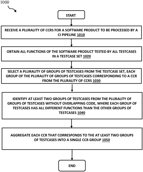
In a recently published patent, International Business Machines Corporation (IBM) presents a method, system, and computer program product that aims to streamline the code change request (CCR) process for continuous integration (CI) pipelines. The patent describes a technique to aggregate multiple CCRs into a single CCR group, increasing efficiency and reducing complexity. The method starts by receiving multiple CCRs for a software product that will be processed by a CI pipeline. It then obtains all the functions of the software product that are tested by the various test cases in a given test case set. Next, the method selects different groups of test cases, with each group corresponding to a specific CCR. The goal is to identify at least two groups of test cases that do not have overlapping code. Finally, the method aggregates all the CCRs corresponding to these non-overlapping groups of test cases into a single CCR group. This patent by IBM addresses an important aspect of software development by proposing a solution to efficiently manage and process code change requests within CI pipelines. Continuous integration is a widely adopted practice in the software industry, enabling teams to combine code changes frequently and detect integration issues early on. Simplifying the CCR process can help streamline development workflows and improve overall productivity. While this patent showcases IBM's commitment to optimizing software development practices, it's important to remember that patent filings do not necessarily indicate immediate product development. Many patents are filed to protect intellectual property and may not always translate directly into consumer products. Nonetheless, IBM's innovative approach to handling CCRs could have significant implications for developers seeking to enhance CI pipelines. As we assess this patent's potential impact, it's worth considering how it would stack up against existing solutions in the market. Are there already similar systems available that address CCR aggregation? How might this patent's approach compare to established competitors' products? Let us know your thoughts and insights in the comments below.
The method, system, and computer program product described herein aggregates code change requests for a continuous integration pipeline. This allows the CI pipeline to process a greater number of changes at one time. The method may include receiving a plurality of code change requests (CCRs) for a software product that are to be processed by the CI pipeline. The method may also include obtaining all functions of the software product tested by all testcases in a testcase set. The method may also include selecting a plurality of groups of testcases from the testcase set, each group of the plurality of groups of testcases corresponding to a CCR from the plurality of CCRs. The method may also include identifying at least two groups of testcases from the plurality of groups without overlapping code. The method may then aggregate each CCR that corresponds to the at least two groups into a single CCR group.
US Patent 11841791
International Business Machines Corporation
A Method to dynamically Switch between Catalog Sharing Protocols
What is this invention?
Dynamic switching of catalog sharing protocols
A method for dynamic switching was found,
To optimize performance when around town.
The catalog indexed data sets,
Intervals were then set,
And protocols switched automatically with a sound!
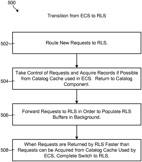
A recent patent filed by International Business Machines Corporation (IBM) has caught the attention of tech enthusiasts. The patent outlines a method to dynamically switch between catalog sharing protocols, which aims to improve the performance of accessing data sets. The patent describes a system that monitors the access to a catalog used for indexing data sets over a period of time. Based on the gathered information, the system divides the time into intervals and determines which sharing protocol would provide the best performance during each interval. The system then schedules the sharing protocols to operate during their respective intervals and switches between them accordingly. In certain scenarios, a hybrid mode is employed, allowing multiple sharing protocols to operate simultaneously until one outperforms the other. While the concept presented in the patent appears promising, it remains to be seen if it will make its way into actual products. Similar sharing protocols are already utilized in various industries, particularly in cloud computing and data storage. Competitors such as Amazon Web Services and Microsoft Azure already offer their own catalog sharing solutions. Therefore, it is important to assess whether IBM's approach presents a significant improvement over existing offerings. Potential applications for this technology could range from improving the efficiency of data centers to simplifying the access and retrieval of large datasets in scientific research or artificial intelligence development. However, the patent primarily focuses on the technical aspects, leaving room for questions regarding its practical implementation. In conclusion, IBM's patent on dynamically switching between catalog sharing protocols holds a promising concept. However, it will be interesting to see if the company translates the idea into a viable product or solution, and if it can outperform existing competitors in the market. What other areas could benefit from dynamically switching between sharing protocols? Share your thoughts in the comments section below!
The method described allows for dynamic switching between different sharing protocols in order to optimize performance. This is done by monitoring access to a catalog which indexes data sets, and then dividing the time into intervals based on which protocol would provide the best performance. The protocols are then scheduled to run during their respective intervals, and switched between when necessary in order to achieve the desired results. In some embodiments, this includes operating in a hybrid mode where multiple protocols operate simultaneously. When one protocol begins to outperform the others, the switch may occur automatically.
US Patent 11841830
Dell Products L. P.
Liquid crystal display has position-adjustable light sources
What is this invention?
Position-adjustable backlight
A liquid crystal display so bright,
The light sources were adjustable in flight.
The current to the magnet carriers made,
Caused them attraction or repelment's trade.
For a better image they would ride and fight!
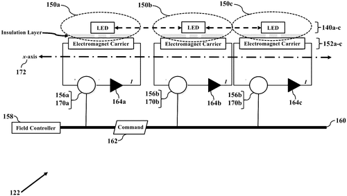
In a recently published patent, Dell Products L. P. reveals a potential innovation in liquid crystal display (LCD) technology - a display with position-adjustable light sources. This development could have significant implications for enhancing image quality and reducing visual artifacts such as halo-effects. The patent describes how the light sources in the display, which can be lamps, LEDs, or other emissive components, are mounted on electromagnet carriers. By applying different currents to these carriers, magnetic fields are generated, causing them to attract or repel one another based on the magnitude and polarity of the currents. This interaction allows for the precise adjustment of the lateral and vertical positions of the light sources, thereby refining the image output of the LCD. While this patent showcases an intriguing advancement, it is important to note that not all patented ideas materialize into actual products. Manufacturers often file patents to protect their intellectual property or to explore possibilities for future technologies. Similar technologies have been introduced in the market, such as local dimming on LED displays, which aim to enhance contrast and reduce halo-effects. Therefore, it remains to be seen whether Dell or any other company will choose to develop and commercialize this particular invention. If brought to fruition, the potential uses for a liquid crystal display with position-adjustable light sources could be extensive. For instance, it could revolutionize display technology in industries that require accurate color reproduction, such as photography, graphic design, or medical imaging. The ability to adjust light positions could also benefit users in everyday scenarios, enabling them to fine-tune image quality in multimedia consumption or gaming experiences. In conclusion, Dell's patent for a liquid crystal display with position-adjustable light sources introduces an interesting concept that, if realized, could have a positive impact on image refinement. However, as with any patent, it is uncertain whether we will see this invention developed into a marketable product. Nevertheless, it sparks a broader discussion on the future possibilities of LCD technology. What potential applications can you envision for an LCD display with adjustable light sources? Share your thoughts in the comments below.
A liquid crystal display has position-adjustable light sources. The light sources may be lamps, LEDs, or other emissive components. The light sources, however, are movable to adjust the locations or positions of their light outputs. The light sources ride upon electromagnet carriers. When currents are applied to the electromagnet carriers, each electromagnet carrier creates a corresponding magnetic field. The magnetic fields cause neighboring electromagnet carriers to attract or to repel, depending on the magnitude/polarity of the currents. The lateral and vertical positions of the electromagnet carriers may thus be adjusted by varying their respective currents and magnetic fields. Because the light sources ride on the electromagnet carriers, the light sources may be moved to refine an image generated by the liquid crystal display.
US Patent 11841586
Dell Products L. P.
Chassis for Housing Information Handling Resources of an Information Handling System Comes with a Ledge and Retention Features
What is this invention?
Interchangeable labeling strip in chassis hem
A chassis for info handling needs,
An enclosure and many bays with ledges,
The labeling strip size fits in the recess,
Retention features keep it under stress.
This system is efficient and so neat!
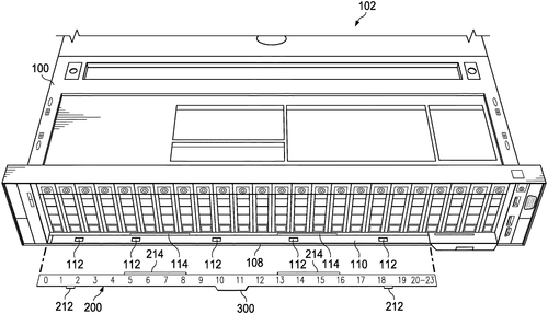
Dell Products L. P. has recently filed a patent for a chassis designed to house information handling resources in an information handling system. The chassis, as described in the patent, features an enclosure with multiple bays to accommodate modular information handling resources. In a rather interesting addition, a hem with a ledge is included, running alongside a portion of the bays. One notable aspect of the Dell patent is the incorporation of a recess in the hem, specifically designed to fit an interchangeable labeling strip. To ensure the strip stays in place, the recess includes multiple retention features, each capable of receiving an engagement feature on the labeling strip. This feature is to retain the labeling strip securely within the recess. While the patent description provides clear details about the configuration of the chassis, it leaves several open questions regarding its potential uses and practicality. How might the interchangeable labeling strip be utilized in different industries? Could this chassis revolutionize the way we organize and identify information handling resources? It is important to note that filing a patent does not guarantee that the invention will be developed into a commercial product. However, Dell's exploration of this concept indicates their commitment to staying at the forefront of innovative technology. Do you think the incorporation of interchangeable labeling strips in an information handling system chassis would be beneficial? Let us know your thoughts in the comments below.
A chassis for housing information handling resources of an information handling system may include an enclosure, a plurality of bays formed within the enclosure, each bay of the plurality of bays configured to receive a corresponding modular information handling resource, and a hem comprising a ledge extending from the enclosure and running proximate to at least a portion of the plurality of bays. The hem may have formed therein a recess sized and shaped in accordance with physical dimensions of an interchangeable labeling strip and a plurality of retention features, each retention feature configured to receive a corresponding engagement feature of the interchangeable labeling strip, in order to retain the interchangeable labeling strip within the recess.
US Patent 11841750
Dell Products L. P.
Operating System Provides Method for Collecting and Transferring Usage Data
What is this invention?
Operating system for collecting and transferring usage data
A system layer of OS was installed,
To configure two hardware components as planned.
Data collection processes at a first location,
Usage data then uploaded to a second station.
Methods and media are provided with care,
So that usage data can be transferred there!

In a recent patent filed by Dell Products L. P., methods, apparatus, and processor-readable storage media for an operating system that collects and transfers usage data have been described. This innovation aims to enhance data collection processes within hardware components, allowing for a more efficient analysis of various characteristics. The computer-implemented method involves configuring multiple hardware components to perform data collection processes, each focusing on specific characteristics of the component. This configuration is carried out by a system layer of an operating system installed on one of these hardware components. Subsequently, the operating system obtains the collected usage data from the configured hardware components over a specified time period. Lastly, the obtained usage data is uploaded to a designated datastore situated at a different location. Although this patent provides an interesting concept, it is important to note that patents do not guarantee that a product will necessarily be developed based on the described technology. In the field of technology, many patents are filed that may never see the light of day as a finished product. That said, this invention has potential practical applications across various industries. Imagine a scenario where this operating system is implemented in the context of an Internet of Things (IoT) network. It could enable efficient data collection and analysis for smart homes to enhance energy consumption optimization or for industries to monitor equipment performance and identify maintenance requirements proactively. However, with existing competitors in the market offering similar solutions, such as Microsoft's Azure IoT Suite and Amazon Web Services' IoT Analytics, it remains to be seen whether Dell will prioritize the development of this technology into a practical product. Do you think an operating system focused on collecting and transferring usage data could make a significant impact in data analysis? Share your thoughts in the comments below!
Methods, apparatus, and processor-readable storage media are provided for operating systems to collect and transfer usage data. An example computer-implemented method includes configuring two or more of a plurality of hardware components to perform respective data collection processes. The data collection processes can be associated with a first location. The configuring can be performed by a system layer of an operating system installed on at least one of the plurality of hardware components. And, the obtained usage data can be uploaded to a datastore that is associated with at least a second location.
US Patent 11841760
Dell Products L. P.
Storing Learned Profile Data Safely After Catastrophic Events
What is this invention?
Persistence of learned profiles
A system for handling info,
Included a processor and store.
It stored learned data in case of a crash,
So it could restore with no rash.
To ensure all was safe to the core!

Dell Products L. P. has recently been granted a patent for an intriguing information handling system. This system is designed to include a processor, physical storage resource, and a non-volatile memory. The processor's main function is to execute instructions for managing learned profile data and responding to catastrophic events. One of the key features of this technology is the ability to store learned profile data at the physical storage resource. This means that the system can gather information over time to create personalized profiles for users. These profiles could potentially be used to enhance user experiences and optimize system performance. In the case of a catastrophic event, such as a system failure or data loss, the processor will kick into action. It will automatically copy the learned profile data from the physical storage resource to the non-volatile memory. This step ensures that valuable user profiles are safeguarded and can be restored in the future. What makes this innovation intriguing is the potential range of applications it could have. Imagine a scenario where a user's laptop suddenly crashes due to hardware failure. With this system in place, the user's personalized settings, preferences, and data could be seamlessly transferred to a backup device, allowing for a smooth continuation of work without any significant disruptions. However, it's important to note that a patent does not necessarily mean a new product is on the horizon. Many patents are filed by companies as a means to protect their intellectual property and may never be developed further. With that in mind, I'd love to hear your thoughts. How do you envision this technology being used in the real world? Can you think of any existing products from competitors that offer similar features? Share your ideas in the comments below.
An information handling system includes a processor, a physical storage resource, and a non-volatile memory other than the physical storage resource. The processor is configured to execute instructions for storing learned profile data at the physical storage resource, in response to detection of a catastrophic event. In response to remediation event for the catastrophic event, the learned profile data is restored from the non-volatile memory.
US Patent 11841773
Dell Products L. P.
File Restores in a Data Domain (DD) File System Implementing a DD Bandwidth Optimized Open Storage Technology (DDBoost) Library
What is this invention?
File restore performance using adaptive prefetching and DDBoost application programming interfaces
A Data Domain file system was found,
With a DDBoost library to abound;
The prefetch queue processor,
Opened the door for success more,
So reads and writes could be soundly compound.

In a recent patent filed by Dell Products L. P., an innovative technology called DD Bandwidth Optimized Open Storage Technology (DDBoost) is described. This technology aims to enhance file restores in a Data Domain (DD) file system by implementing a DDBoost library that translates application read and write requests to DDBoost application program interfaces (APIs). One interesting feature of this invention is the inclusion of a prefetch queue processor that creates an intent to read the file. The application then passes the file handle and the destination handle where the data needs to be read into. As the queue is processed, the prefetch for the request (handle/offset/length) is sent to the file server. The file system then works to open the file and load it into memory. When the read request for the same file reaches the file system, the file data is retrieved from memory and written to the destination handle. Additionally, an extended DDBoost API expression is defined to transmit the current path and destination path to the application. While this patent presents an intriguing concept, it's important to remember that not all patents result in actual product development. It remains to be seen whether Dell will bring this technology to market and how it will compare to existing competitors' products. Nevertheless, if successfully implemented, this innovative approach to file restores could enhance efficiency and data access in Data Domain file systems. So, what do you think? Are you excited about the potential of this patent? Do you see any practical applications for this technology in your work or personal life? Let us know in the comments below!
This text describes how a Data Domain (DD) file system implementing a DD Bandwidth Optimized Open Storage Technology (DDBoost) library can translate application read and write request to DDBoost APIs. A prefetch queue processor creates an intent to read the file. The application passes the file handle of the file, and the destination handle where the data must be read into. As the queue is processed, the prefetch for the request (handle/offset/length) is passed to the file server. The filesystem processes the request to open the file to load into memory. As the read request for same file reaches filesystem, it reads data from memory for writing to destination handle. An extended DDBoost API expression is defined to pass current path and destination path to application.
US Patent 11841775
Amazon Technologies, Inc.
Calibrating Radar Systems to Remove Unwanted Effects of Mutual Coupling
What is this invention?
Calibrating radar systems for movement detection
A radar system must be calibrated,
For poor RF isolation is dreaded.
Noise floor should be low,
Gain of both set just so,
To keep the environment protected.
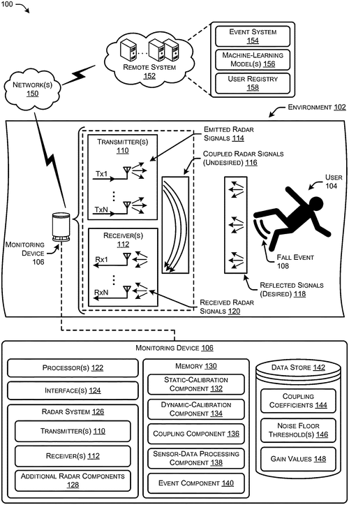
Amazon Technologies, Inc. has recently filed a patent for a groundbreaking technique that could significantly improve the performance of radar systems in electronic devices. This exciting innovation addresses the issue of mutual coupling, where radar receivers absorb energy emitted from nearby transmitters, causing interference and degrading radar performance. In devices with multiple transmit antennas and multiple receive antennas, also known as Multiple-Input Multiple-Output (MIMO) radar systems, poor radio frequency (RF) isolation is a common problem. This lack of isolation can lead to non-linearities in the receiver chain, resulting in increased receiver noise floor and a decline in radar accuracy. The patent describes a calibration process that aims to eliminate the effects of poor RF isolation by first identifying the receiver noise floor in the device's environment. Once the noise floor is determined, the transmitter and/or receiver gain can be fine-tuned accordingly, effectively removing the impact of poor isolation and improving the accuracy of the radar system's object representations. This invention has the potential to revolutionize the capabilities of radar systems in electronic devices, enabling more precise object detection and recognition. The applications of such improved radar technology are vast, ranging from autonomous vehicles to gesture-based interfaces or even enhanced security systems. While this patent represents a significant step forward in radar technology, it is important to note that not all patented innovations make it to market. The competitive landscape is fierce, with companies like Google, Tesla, and Apple investing heavily in radar-based sensing technologies. It remains to be seen whether Amazon Technologies, Inc. will turn this patent into a marketable product. In the comments below, we'd love to hear your thoughts on this patent. Can you imagine any potential uses for this radar calibration technique? How do you think it stacks up against competitors' offerings in the market?
This document describes techniques for calibrating radar systems to remove undesirable effects of mutual coupling where receivers absorb energy emitted from nearby transmitters. Poor RF isolation may lead to non-linearities in the receiver chain, which in turn leads to an increase in receiver noise floor that degrades the radar performance. The calibration process includes identifying the receiver noise floor for the environment of the electronic device and adjusting transmitter and/or receiver gain such that the effects of poor RF isolation are substantially removed from representations of objects in the environment created using the radar system.
US Patent 11841455
Amazon Technologies, Inc.
Simulating Network Outages for Optimal Performance
What is this invention?
Simulated network outages to manage backup network scaling
A system was configured to simulate,
Outages of network resources so fine.
The control plane moved the workloads around,
To a secondary region they were bound.
After it was done, they went back home,
And performance had been tracked on their roam.
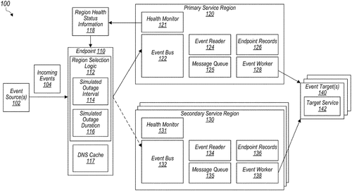
Amazon Technologies, Inc. has recently filed a patent for a system that aims to simulate outages of network resources. This system, if implemented, would provide a control plane for computing resources within a provider network. The control plane would be able to create simulated outages in a primary region that hosts different computing resources. During these outages, the system would automatically move the workloads of these computing resources to one or more secondary networks, and track the performance of these secondary regions. Once the simulated outages are completed, the system would then move the workloads back to the primary region. This patent by Amazon presents an interesting concept that could potentially have significant implications for network providers. By simulating outages and testing the performance of secondary networks, they could gain valuable insights into their network infrastructure's robustness and resilience. This could ultimately lead to more reliable and efficient services being offered to customers. While the idea behind this patent is intriguing, it is important to remember that not all patented concepts become practical products. Competitors such as Microsoft and Google already offer similar services that allow users to distribute their computing resources across multiple regions for redundancy and fault tolerance. The key question remains: Will Amazon be able to turn this patent into a tangible product that can outperform its competitors? What do you think? Would you be interested in using a service that simulates outages and automatically switches your computing resources to secondary networks? Share your thoughts in the comments below.
The system is configured to simulate outages of network resources. The control plane is configured to cause the simulated outages of a primary region of the plurality of regions selected to host the plurality of different computing resources. During the simulated outages, the control plane moves respective workloads of the plurality of different computing resources to be performed in one or more secondary networks and tracks a performance of the one or more secondary regions hosting the moved respective workloads of the plurality of computing resources. After completing individual ones of the simulated outages, the control plane moves back each workloads back to its original location on the primary region.
US Patent 11841780
Amazon Technologies, Inc.
New Hardware Accelerator Can Execute Complex Instructions Faster
What is this invention?
Instructions with multiple memory access modes
A hardware accelerator so great,
The instruction decoder's first rate.
It can map a schema
And the engine to steam,
To execute instructions straight.
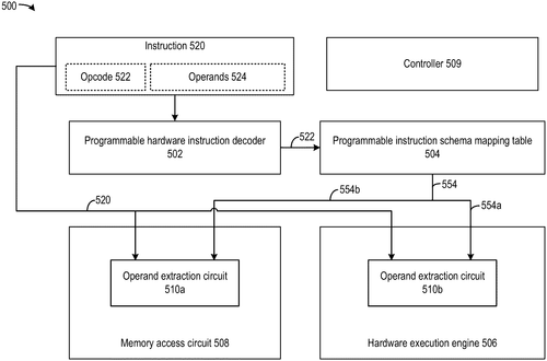
Amazon Technologies, Inc. has recently filed a patent that outlines a potentially groundbreaking hardware accelerator. The patent describes a device that includes a programmable hardware instruction decoder, a programmable instruction schema mapping table, a hardware execution engine, and a controller. The hardware accelerator is designed to extract relevant information from instructions and execute them based on the extracted data. While the technical details of the patent may be challenging for the average reader, the implications are significant. If successfully developed, this hardware accelerator could greatly enhance the speed and efficiency of computing devices. By utilizing a content addressable memory (CAM) and programmable features, the device has the potential to decode and execute instructions more rapidly. In the competitive world of technology, speed is often a differentiating factor. This patent from Amazon Technologies puts the company in an advantageous position, potentially enabling them to develop products that outperform their competitors. However, it's important to note that patent filings do not guarantee the creation of an actual product. In terms of potential applications, this hardware accelerator could revolutionize industries that require rapid data processing, such as artificial intelligence, machine learning, and high-performance computing. By improving instruction decoding and execution, devices powered by this technology could potentially offer faster and more efficient solutions. As exciting as this patent sounds, it is crucial to remember that not all patents translate into tangible products. Inventions like this often face numerous challenges during the development and commercialization process. Therefore, while it's fascinating to envision the possibilities, it remains uncertain whether this patent will lead to a real-world product. What are your thoughts on this recent patent? Do you believe Amazon Technologies will bring this hardware accelerator to life, setting a new benchmark in computing performance? Share your insights and opinions in the comments below.
This document describes a hardware accelerator that includes a programmable instruction decoder, a programmable instruction schema mapping table, and a hardware execution engine. The accelerator can receive an instruction and extract the first opcode from the instruction. Based on the first opcode, the accelerator can obtain a first definition of a first operand from the instruction schema mapping table. The accelerator can forward the instruction and the first definition to the hardware execution engine to control the hardware execution engine to extract the first operand from the instruction based on the first definition. Finally, based on this information,the acceleration can execute the instructions accordingly.
US Patent 11841792
Amazon Technologies, Inc.
Distributed Database Management Systems Keep Collections of Items Spreading Across Multiple Partitions in Sync
What is this invention?
Index update pipeline
A distributed database system,
Maintains items in multiple partitions.
Index structures span one or more,
Changes to the data are what's in store.
With replication logs and acknowledgments galore!
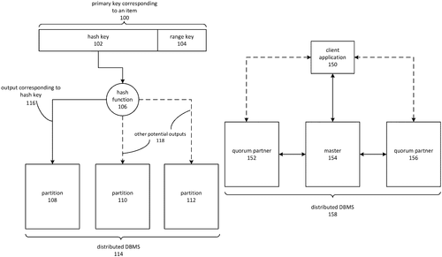
Amazon Technologies, Inc. has recently filed a patent for a distributed database management system that aims to enhance the efficiency and reliability of maintaining collections of items across multiple partitions. In this patent, Amazon proposes the use of index structures that correspond to items on one or multiple partitions and can be replicated. Whenever changes are made to the data in the system, updates are automatically made to the relevant index structures. The innovation lies in the compilation of these changes into an instruction set that can be applied to the index structures. Prior to transmission, the instructions are stored in in-memory buffers, ensuring a smooth and seamless process. For increased reliability, replication logs are combined with an acknowledgment mechanism to guarantee the accurate transmission of instructions to the affected partitions. Although this patent showcases the potential for more efficient and scalable distributed database management systems, it is important to consider whether this invention will actually make its way into a practical product. The fact that it is currently at the patent stage means that Amazon is exploring this concept, but there is no guarantee that it will be implemented in their existing infrastructure or services. Competitors in the database management space, such as Oracle and Microsoft, already offer advanced solutions for distributed systems. These companies have a strong foothold in the market with their mature products. It will be interesting to see how Amazon's patent, if developed into a product, can compete against these established alternatives. In terms of potential uses, this innovation could greatly benefit large-scale platforms that handle vast amounts of data across multiple partitions, such as e-commerce websites or social media networks. The ability to efficiently update index structures and replicate changes in a reliable manner could improve search functionality, reduce latency, and enhance overall performance for users. Ultimately, it remains to be seen whether Amazon will turn this patent into a tangible product. However, the concept itself presents an intriguing possibility for advancing the field of distributed database management systems. What other industries or applications could benefit from more efficient distributed database management systems? Share your thoughts in the comments below.
Distributed database management systems maintain collections of items spanning multiple partitions. Index structures correspond to items on one partition or to items on multiple partitions. Item collections and indexes may be replicated. Changes to the data maintained by the distributed database management system may result in updates to multiple index structures. The changes may be compiled into an instruction set applicable to the index structures. In-memory buffers contain instructions prior to transmission to affected partitions. Replication logs are combined with an acknowledgment mechanism for reliable transmission of the instructions to the affected partitions
US Patent 11841844
Amazon Technologies, Inc.
Stored procedures keep your materialized views current
What is this invention?
Stored procedures for incremental updates to internal tables for materialized views
A stored procedure is the key
To update a materialized view, you see.
It will create some tables,
And make updates when it's able;
The process happens automatically.
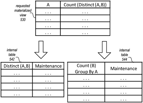
Amazon Technologies, Inc. has recently been granted a patent for a new method of updating materialized views in a database. According to the patent description, this technology generates stored procedures that can perform incremental updates to a materialized view. In simpler terms, when a request to create a materialized view is received, the technology creates one or more internal tables from the original database. Then, a stored procedure is generated which, when executed, updates the materialized view. This stored procedure can also obtain changes to the database that were not included in the internal tables and update them as well. The stored procedure can be performed automatically or in response to specific requests. While this patent certainly sounds promising and could potentially have significant implications for database management, it is important to consider its practicality. As with any patent, the mere existence of a new technology does not necessarily guarantee its successful implementation in a marketable product. We must wait and see if Amazon Technologies, Inc. takes steps to bring this innovation to life. In the world of database management, there are already several competitors offering similar solutions. Companies like Oracle and Microsoft already provide tools for the creation and maintenance of materialized views in databases. The challenge for Amazon will be to differentiate their technology and offer unique features that can capture the attention of potential customers. If this patent becomes a reality, it could have various applications across industries that heavily rely on databases. For example, financial institutions could use this technology to efficiently update materialized views for real-time market data, while e-commerce companies could benefit from faster and more accurate product inventory management. As we eagerly wait to see how this patent progresses, I would love to hear your thoughts on the potential impact of such a technology. Do you believe this innovation could revolutionize database management? Or do you see any potential downsides or limitations that should be considered? Share your insights in the comments below.
Stored procedures are used to automatically update a materialized view of a database when changes are made to the data. When a request is received to create a materialized view, one or more internal tables are created from the database. The stored procedure then generates an update to the materialized view that includes any changes obtained from the database. This process is performed automatically and in response to requests.
US Patent 11841848