Most innovative companies for 01/31/2023 (new inventions)
Exciting new inventions from Honda Motor Co., Ltd., Seiko Epson Corporation, Toyota Motor Engineering & Manufacturing North America, Inc., Ford Global Technologies, Llc And Hyundai Motor Company
This is a weekly article summarizing a handful of inventions from the most innovative companies in the world. The summaries are created by an A.I. and proof-read by a human before publication. Attempts are made to ensure accuracy of the descriptions, but it is very much a work in progress. Each invention description is preceeded by a poem about the invention that is written by the A.I. I have found the limerick is actually quite good at explaining the invention in simple terms. Enjoy!
HONDA MOTOR CO., LTD.
New catalyst composition for hydrogen evolution reaction
What is this invention?
Catalyst compositions including metal chalcogenides, processes for forming the catalyst compositions, and uses thereof
A present disclosure, it's true
Of metal chalcogenides too
For catalytic sites to thrive
It needs electrolyte and amphiphile
Devices for hydrogen evolution reaction, so new!
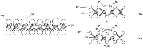
Honda Motor Co., Ltd. has just unveiled an exciting new catalyst composition that could revolutionize the way we produce conversion products. The new catalyst composition includes metal chalcogenides, electrolyte materials and amphiphile materials, and can be used in processes for producing conversion products with enhanced catalytic active sites. This breakthrough technology from Honda promises to make hydrogen evolution reactions more efficient than ever before - allowing us to create a wide range of energy-efficient products without sacrificing performance or reliability. With this advanced catalyst composition, Honda is paving the way for a greener future!
The present disclosure generally relates to catalyst compositions including metal chalcogenides, processes for producing such catalyst compositions, processes for enhancing catalytic active sites in such catalyst compositions, and uses of such catalyst compositions in, e.g., processes for producing conversion products. In an aspect, a process for forming a catalyst composition is provided. The process includes introducing an electrolyte material and an amphiphile material to a metal chalcogenide to form the catalyst composition. In another aspect, a Catalyst composition is provided. The Catalyst composition includes a metal chalcogenide, an electrolyte material, and an amphiphile material. Devices for hydrogen evolution reaction are also provided.
US Patent 11565247
Seiko Epson Corporation
3D Shaped Article Production Method Stacks Layers to Form a Stacked Body - Sintering Follows
What is this invention?
Three-dimensional shaped article production method
A three-dimensional shaped article's made
By stacking layers, a stacked body's laid
The first layer is formed
Using particles and binder warm
In the end after sintering it stays

Seiko Epson Corporation has created a revolutionary three-dimensional shaped article production method that will revolutionize the way we create 3D objects. This method involves stacking layers to form a stacked body, then using a first layer formation step of forming a first layer on a support by supplying a first composition containing first particles and binder and second layer formation step of forming one or more additional layers on the first layer by supplying second particles and binder. After this separation step, the second layer is sintered for extra strength and durability. This innovative new process makes it easier than ever before to produce strong, durable three-dimensional shaped articles in an efficient manner. Whether you need something small like jewelry or large like furniture - this process can be used to quickly create whatever you need with ease! With Seiko Epson's Three-dimensional Shaped Article Production Method, creating 3D objects has never been simpler!
The three-dimensional shaped article production method for producing a three-dimensional shaped article by stacking layers to form a stacked body includes a first layer formation step of forming a first layer on a support by supplying a first composition containing first particles and a binder, a second layer formation step of forming a second layer composed of one layer or a plurality of layers on the first layer by supplying a second composition containing second particles and a binder, and an separation step of separating the second layer from the support through the first layer. After the separation step, the sintering step is performed.
US Patent 11565314
Toyota Motor Engineering & Manufacturing North America, Inc.
Remove Material From Ultrasound Directing Element With This Simple Method
What is this invention?
Sanding apparatus with multiple part engagement members
A method for sanding was found,
To mount the ultrasound element to a block on the ground.
An engagement member moved from release to engage,
The mounting block then along the base it did range.
Material removed with great ease,
By using the sanding surface as you please!
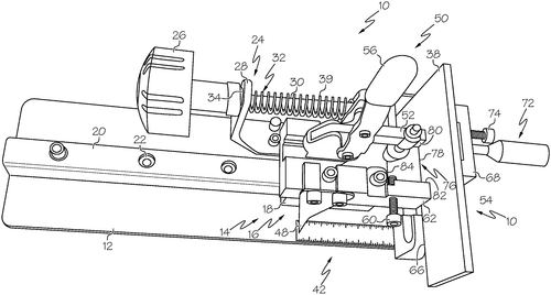
Toyota Motor Engineering & Manufacturing North America, Inc. has just released an exciting new sanding apparatus with multiple part engagement members. This innovative tool is designed to quickly and efficiently remove material from the surface of ultrasound directing elements made of plastic materials. The mounting block includes an engagement member which can be moved between a release position and an engagement position, allowing for precise control over the amount of material being removed from the element. The base of the sanding apparatus also helps ensure that all surfaces are properly treated during use - simply move it along the base to bring any surface into contact with the sanding surface! Thanks to this intuitive design, you can now get perfect results every time when removing plastic materials from ultrasound directing elements. Make sure to check out Toyota’s new Sanding Apparatus with Multiple Part Engagement Members today!
The method includes mounting the ultrasound directing element to a mounting block of a sanding apparatus. The mounting block includes an engagement member that moves from a release position to an engagement position thereby engaging the ultrasound directing element. The mounting block is moved along a base of the sanding apparatus bringing a surface of the ultrasound directing element into contact with a sanding surface. Material is removed from the surface of the ultrasound directing element using the sanding surface.
US Patent 11565368
Toyota Motor Engineering & Manufacturing North America, Inc.
Robot Base Assembly Supports Robot Above Floor, with Clamp Assembly That Engages Locating Component
What is this invention?
Robot base assemblies
A robot base assembly was made
To support a robot above the floor grade
The clamp assembly could move
From disengaged to approve
And when it did, the lock would be engaged
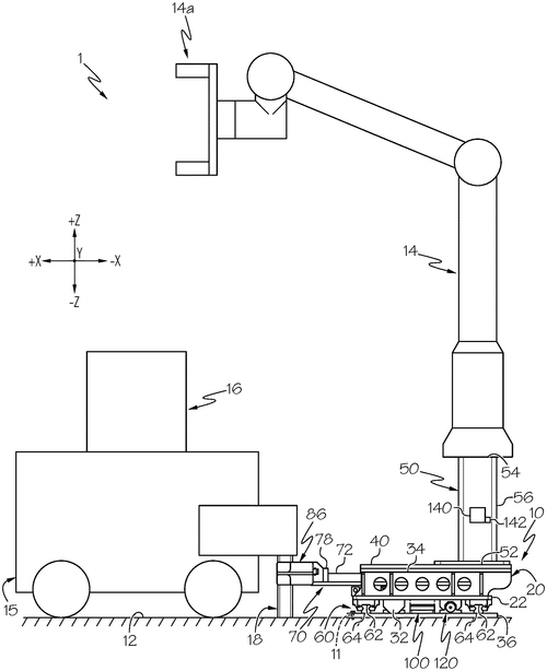
Robots are becoming increasingly commonplace in many industries, and Toyota Motor Engineering & Manufacturing North America, Inc. has just unveiled a revolutionary new robot base assembly that will make the process of working with robots even easier. This advanced robot base assembly supports a robot above the floor and includes a clamp assembly that engages with the work piece’s locating component. The lock mechanism switches from an unlocked state to a locked state when the clamp assembly moves from its disengaged state to its engaged state - making it easy to secure your robotic arm in place for optimal efficiency. With this new technology, you can easily move your robotic arm around without having to worry about it slipping or falling off during operation!
The robot base assembly described in the patent supports a robot assembly above a floor. The clamp assembly is movable between an engaged state and a disengaged state, and the lock mechanism switches from the unlocked state to the locked state in response to the clamp assembly moving from the disengaged state to the engaged state.
US Patent 11565400
SEIKO EPSON CORPORATION
A Plasticizing Apparatus for Plasticsizing a Material to Form a Molten Material
What is this invention?
Plasticizing apparatus, plasticizing method, and three-dimensional shaping apparatus
A plasticizing apparatus was made
With a screw in columnar shape displayed
The groove had a channel,
For material to travel
And the recess provided heat insulation grade.
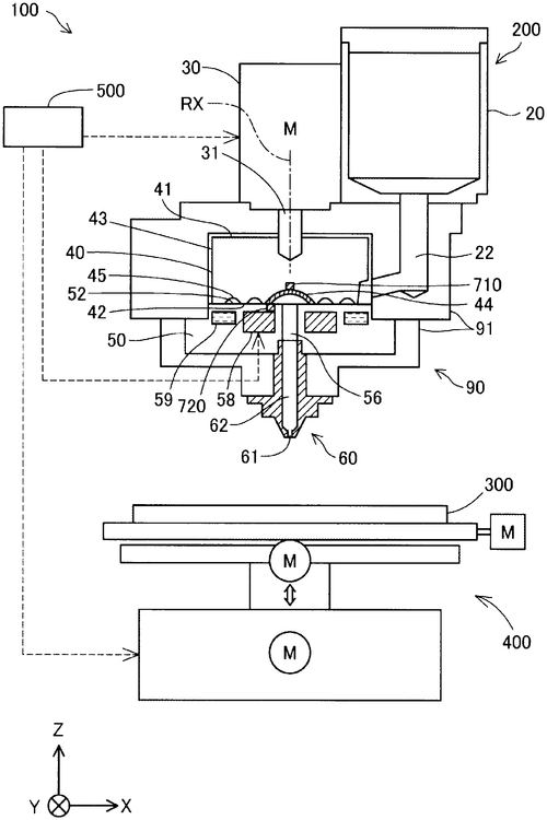
SEIKO EPSON CORPORATION is proud to review the invention of a new plasticizing apparatus, plasticizing method, and three-dimensional shaping apparatus. This revolutionary device makes it easier than ever before to form molten material into desired shapes. The apparatus consists of a screw in a columnar shape with a groove formed face that contains the material flow channel, along with a barrel having an opposed face which houses the sending out hole for sending out the molten material at its center. The unique feature of this device is its heat insulating portion which has lower thermal conductivity than an outer circumferential portion in the screw. This helps to maintain consistent temperatures as well as control how quickly or slowly materials are melted down - perfect for getting precise results every time! With this new tool from SEIKO EPSON CORPORATION, you can easily create complex 3D shapes without breaking your budget or spending too much time on setup and cleanup.
The patent describes a plasticizing apparatus, which includes a screw in a columnar shape with a groove formed face. A material flow channel is formed in the groove, and includes a groove portion that is to be supplied with the material. A barrel opposed face is also provided, and has a screw opposed face. A sending-out hole is formed at center of the barrel, and a heating portion heats the material flowing through the material flow channel. The recess in the screw provides better heat insulation for the groove portion than an outer circumferential portion of the screw would provide.
US Patent 11565467
Seiko Epson Corporation
An accommodating body that includes a first buffering material
What is this invention?
Accommodating body, buffering material, method for manufacturing buffering material, and buffering material manufacturing apparatus
There was a body quite accommodating,
With first bottom portion and buffering.
The web contained fibers so fine,
Bonded with material divine,
And the pressure receiving surface at its ending.
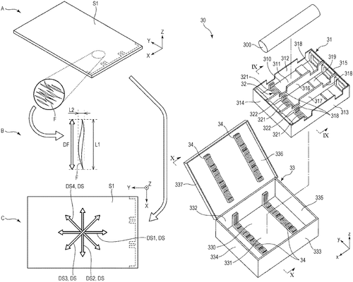
Seiko Epson Corporation has developed an innovative new accommodating body that is designed to protect the items inside it from damage. This accommodating body features a first buffering material, which consists of at least one sheet-shaped web containing fibers and a bonding material that binds them together. The fibers in this web are oriented in the plane direction of the first sheet-shaped web, ensuring maximum protection for whatever is being stored within. This buffering material not only provides superior protection against shocks and impacts, but also helps to reduce noise levels when storing items such as electronics or other sensitive materials. Additionally, its unique orientation ensures that there will be no pressure points on the accommodated article due to uneven weight distribution. The Seiko Epson Corporation Accommodating Body with Buffering Material offers unparalleled protection for your valuable items while maintaining a lightweight form factor - perfect for anyone looking for reliable storage solutions!
The patent describes an accommodating body that includes a first bottom portion, a first buffering material, and a first pressure receiving surface. The first buffering material has a first sheet-shaped web that contains fibers and a bonding material that bonds the fibers. In the first sheet-shaped web, the fibers are oriented in a plane direction of the first sheet-shaped web. The first pressure receiving surface is located at an end surface of the first sheet-shaped web.
US Patent 11565498
SEIKO EPSON CORPORATION
Physical Quantity Detection Device Detects Electrostatic Capacitance
What is this invention?
Physical quantity detection device and printing apparatus
A physical quantity detection device,
With a container for the dielectric piece,
The first and second electrodes too,
To detect an electrostatic capacitance true.
For |Zc|/|Z1|+|Zc|>|Zc|/|Z2|+ | Zc|| to be satisfied with glee!
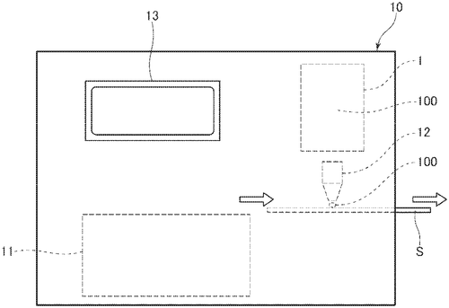
Today, we are excited to introduce the Physical Quantity Detection Device from SEIKO EPSON CORPORATION. This device is designed for detecting physical quantities such as temperature and humidity with great accuracy. The device consists of a container, two electrodes, and an electrostatic capacitance detector that measures the difference in impedance between when a detection object is present or not. This allows for accurate readings regardless of environmental conditions. Furthermore, the relationship |Zc|/|Z1|+|Zc|>|Zc|/|Z2
The physical quantity detection device includes a container that accommodates a detection object formed of a dielectric. A first electrode is provided at an outer side of the container, and a second electrode is provided separately from and to face the first electrode. The electrostatic capacitance detector detects an electrostatic capacitance between the first electrode and the second electrode. The electrostatic capacitance detector includes a waveform generation source coupled to the first electrode and a voltage detection circuit coupled to the second electrode. A relationship of |Zc|/|Z1|+|Zc|>|Zc|/|Z2|+|Zc| is satisfied in which |Zc| is an absolute value of an input impedance of the electrostatic capacitance detector, |Z1| is an absolute value of an impedance when the detection object is present between the first electrode and the second electrode, and |Z2| is an absolute value of an impedance when no detection object is present between the first electrode and the second electrodes.
US Patent 11565531
Seiko Epson Corporation
A Recording Device As A Processing Device - Your Media Needs No Limits!
What is this invention?
Processing device and recording device
A recording device did require
A unit for the medium to acquire
The shaft was inside,
And wound round with pride
When separated it would inspire.
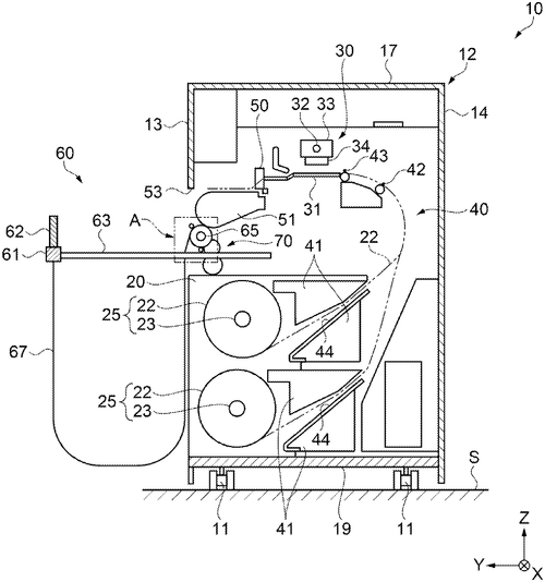
Introducing the revolutionary new Processing Device and Recording Device from Seiko Epson Corporation. This device is perfect for anyone who needs to record data on a medium, as it includes a recording unit and a medium accommodating unit that can accommodate the discharged medium. The medium accommodating unit consists of an operating portion provided separately from the housing, which allows you to easily feed the accommodating member from its rotating shaft when needed. Additionally, this device is designed with portability in mind - when not in use, all components fit inside the housing so you can take your recordings with you wherever you go! With this innovative technology at your disposal, recording data has never been easier or more convenient.
The patent describes a recording device, which includes a recording unit and a medium accommodating unit. The medium accommodating unit accommodates a medium discharged from the housing. The rotating shaft is provided inside the housing and to which one end of the accommodating member is connected. The operating portion is provided separably from the housing and to which the other end of the accommodating member is connected. The accommodating member is wound around the rotating shaft and accommodated inside the housing when the operating portion is mounted on the housing. The accommodating member is fed from the rotating shaft so that the medium is accommodated when the operating portion is separated from the housing.
US Patent 11565540
SEIKO EPSON CORPORATION
Printing Device Keeps Your Devices Safe and Secure
What is this invention?
Printing device
A printing device had an inside,
Which was neatly hidden away.
But when the cover was open wide,
The operation unit displayed.
It held a state that toggled with ease,
Thanks to its clever use of keys!
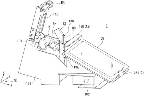
SEIKO EPSON CORPORATION has just released a revolutionary new printing device that is sure to revolutionize the way we print. This device features a casing with an opening and closing cover, as well as an operation unit that can be exposed or hidden depending on whether the cover is open or closed. Additionally, this device comes with a holding unit that can switch between two states - one for holding an information processing device and another for releasing it - in response to commands from the operation unit. This new printing device provides users with unprecedented control over their printing needs. With its easy-to-use interface and versatile design, you'll have no trouble getting your documents printed quickly and efficiently every time!
A printing device includes an operation unit, a casing, and a holding unit. The operation unit is provided in the casing and not exposed outside of the casing when the cover is closed. When the cover is open, the operation unit is exposed outside of the casing. The holding unit has a state that switches based on an operation accepted by the operation unit.
US Patent 11565542
Ford Global Technologies, LLC
Wheel Assembly Offsets First Bore and Central Axis
What is this invention?
Wheel assemblies for motor vehicles
A wheel assembly had a hub,
The stud was split in two parts near it,
The nut then got threaded on tight,
It moved from one to the other side,
To keep the wheel turning just right.
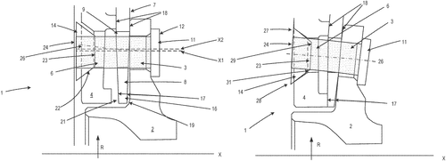
Ford Global Technologies, LLC has just unveiled their newest innovation in wheel assemblies for motor vehicles. This new assembly features a wheel hub with a bore and a wheel with another bore that are offset from each other. The two bores are connected by the wheel stud which is then secured to the hub using a wheel nut. What makes this system so innovative is that when the nut is tightened, it causes the first portion of the stud to move from its initial position relative to an axis of rotation of the hub into its second position - thus securely fixing it in place. This revolutionary design not only makes attaching wheels easier than ever before but also ensures they stay firmly attached no matter what kind of terrain you're driving on. So if you're looking for reliable and easy-to-install wheels for your vehicle, look no further than Ford's new Wheel Assembly system!
The wheel assembly includes a hub, a stud, and a nut. The stud has first and second portions that are proximate to the hub. The nut is threaded onto the stud and can move from a first position relative to an axis of rotation of the hub to a second position relative to the axis of rotation when tightened.
US Patent 11565546
HONDA MOTOR CO., LTD.
A Vehicle Height Adjusting Apparatus That Ensures Your Seat Is Always At The Right Height
What is this invention?
Vehicle height adjusting apparatus
A vehicle with a hydraulic seat
Could adjust its height with quite a feat,
The motor and control
Would measure the load,
And that's how it adjusts so neat!
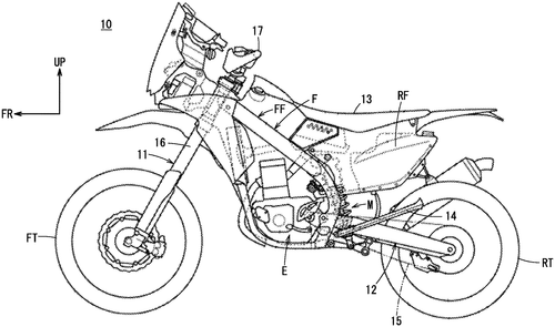
Honda Motor Co., Ltd. has just unveiled their latest innovation - the Vehicle Height Adjusting Apparatus. This apparatus uses hydraulic pressure to adjust the height of a seat on a saddle-type vehicle, with an oil supplying portion powered by a motor and controlled by a control section that estimates the load applied to the vehicle height adjusting member based on current supplied to the motor and stroke correspondence quantity. With this invention, Honda is taking vehicular comfort to new heights! The Vehicle Height Adjusting Apparatus is perfect for anyone looking for more comfortable driving experiences. Whether you're tall or short, this apparatus can be adjusted so your seat fits perfectly - no more craning your neck or slouching in discomfort! The adjustable design also makes it great for sharing vehicles between family members of different heights as well as accommodating passengers who may have mobility issues. Whether you're cruising around town or hitting up some off-road trails, Honda's Vehicle Height Adjusting Apparatus will make sure your ride stays comfortable all along the way!
A vehicle height adjusting apparatus according to one aspect includes a vehicle height adjusting member that adjusts height of a seat of a saddle-type vehicle, using hydraulic pressure. An oil supplying portion that supplies oil to the vehicle height adjusting member, using a motor is also included. The control section estimates a load applied to the vehicle height adjusting member, from a current supplied to the motor and stroke correspondence quantity of the vehicle height adjusting member. And based on the estimated load, the control section controls the oil supplying portion to adjust the Height of Seat.
US Patent 11565566
FORD GLOBAL TECHNOLOGIES, LLC
Suspension assembly for vehicle includes stabilizer bars that can be in three configurations
What is this invention?
Invertible stabilizer bar and system incorporating the same
A suspension assembly for a car,
Had an inverter housing not far.
It had stabilizers two,
One on each side of the view,
And an actuator that could move it by bar.
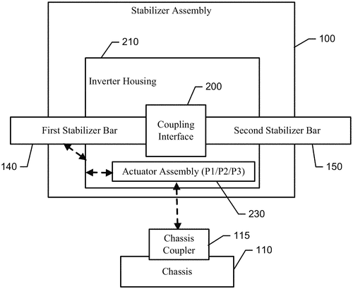
FORD GLOBAL TECHNOLOGIES, LLC has developed a revolutionary new suspension system for vehicles that can be adjusted to suit any terrain. The Invertible Stabilizer Bar and System incorporates an inverter housing and an actuator assembly that allows the user to adjust the stabilizer bar between three different states – connected, disconnected, and inverted. With this technology, drivers are now able to easily switch between soft suspensions for off-road driving or tight suspensions for highway cruising with just the flip of a switch! Not only does this provide maximum comfort no matter what road you’re on but it also increases stability and handling performance in all conditions. So if you’re looking for a vehicle that can handle anything from city streets to mountain trails, then look no further than FORD GLOBAL TECHNOLOGIES’ Invertible Stabilizer Bar and System!
The suspension assembly may include a first stabilizer bar operably coupled to a first wheel on a first side of the vehicle, a second stabilizer bar operably coupled to a second wheel on a second side of the vehicle, and an inverter housing. The actuator assembly may be operable to arrange the first stabilizer bar and the second stabilizer bar in a selected one of connected state, disconnected state, and inverted state. The inverter housing may be alternately constrained to one of the first stabilizer bar or chassis coupler based on position of the actuator assembly.
US Patent 11565567
Ford Global Technologies, LLC
This system protects you from contagious diseases
What is this invention?
Systems and methods to protect the health of occupants of a vehicle
A vehicle's occupants health,
We must protect from contagious stealth.
If an individual shows a symptom,
The monitoring apparatus will issue them
An advisory to pick another seat.
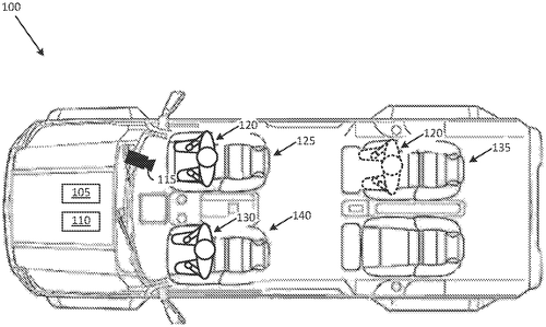
The world has changed drastically in the past year, and it’s no surprise that the automotive industry is adapting to meet new health challenges. Ford Global Technologies, LLC has just released a revolutionary system designed to protect vehicle occupants from contagious diseases. Using a combination of spatial separation and air flow patterns, this system can detect symptoms of disease in an individual entering or already seated in a vehicle. It then identifies an alternate seat with enough distance between them and the first occupant to provide protection against contagious illnesses. The system also adjusts airflow patterns inside the car to further ensure maximum safety for all passengers. This innovative technology is sure to make traveling safer than ever before - not only for individuals but also for families who are looking for peace of mind when they hit the road together. With this new invention from Ford Global Technologies, LLC, you can rest assured that your health will be protected while you travel!
This disclosure generally relates to systems and methods for protecting the health of occupants of a vehicle. In one example, a health monitoring apparatus in the vehicle evaluates an individual and detects a symptom of a contagious disease. The individual may be already seated in a first seat in the vehicle or intends to enter the vehicle. If it is determined that the individual should occupy another seat, then the health monitoring apparatus can issue an advisory to the individual to occupy that seat. In another example, if it is determined that airborne particles from an infectious agent may be present in the vehicle, then the health monitoring apparatus can adjust an airflow pattern in order to protect various occupants of the vehicle against infection by this agent.
US Patent 11565571
Hyundai Motor Company
AUTOMATICALLY SWITCHING AIR CONDITION FOR BETTER ENERGY EFFICIENCY
What is this invention?
Apparatus and method for controlling air conditioning of vehicle
A vehicle's air conditioning here,
Is controlled with a method so clear.
The pollutant and CO2,
Are measured by the sensor true,
To switch auto mode no need to fear!
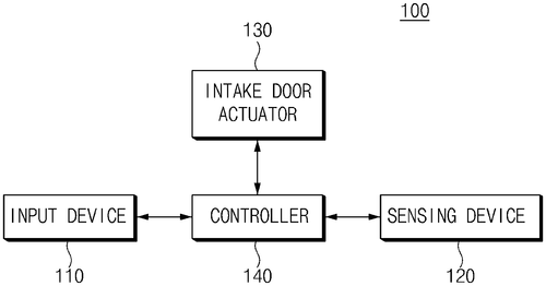
We all know the importance of keeping our vehicles clean and healthy, but what about the air inside? Hyundai Motor Company has developed an innovative apparatus and method for controlling air conditioning in a vehicle to ensure that passengers are breathing in clean, pollutant-free air. This system uses at least one sensor to measure both pollutant concentration and carbon dioxide concentration within your car. The controller then determines an optimal in-vehicle air condition based on this data, automatically switching an in-vehicle air circulation mode accordingly. With this new technology from Hyundai Motor Company, you can feel assured that you’re getting the best possible quality of air while driving!
The apparatus and method for controlling air conditioning of a vehicle are provided. The apparatus includes a sensing device that measures a pollutant concentration and a carbon dioxide concentration in the vehicle using at least one sensor. A controller determines an in-vehicle air condition based on the pollutant concentration and the carbon dioxide concentration, and automatically switches an in-vehicle air circulation mode based on a determination result.
US Patent 11565573
TOYOTA MOTOR ENGINEERING & MANUFACTURING NORTH AMERICA, INC.
Simulation of Rev-Matching in Hybrid Electric Vehicles Provides Increased Engine Response
What is this invention?
Sequential simulated gear ratio calculation and rev-matching in a hybrid electric vehicle
A hybrid electric vehicle, oh my!
Its rev-matching will make you fly.
With engine speed increased
While downshifting not ceased,
You'll be driving in style 'til you die.
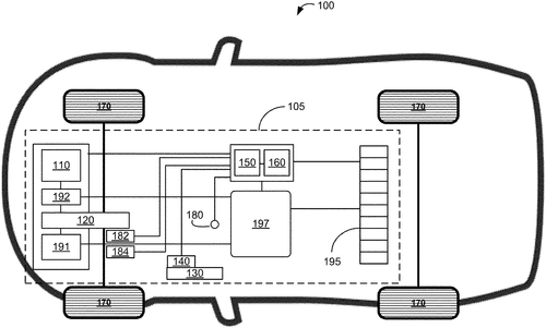
Drivers of hybrid electric vehicles (HEVs) now have an even better driving experience thanks to a new invention from Toyota Motor Engineering & Manufacturing North America, Inc. The Sequential Simulated Gear Ratio Calculation and Rev-Matching system provides increased engine response while downshifting during acceleration. With this innovation, the transmission of an HEV includes an electronic control unit that controls the speed of the engine to simulate gears. When a driver shifts from one simulated gear to a lower one, the speed of the engine is increased in order to provide rev-matching for improved performance. This process is based on specific gear ratios associated with each simulated gear which are used to calculate a target engine speed so that drivers can enjoy smoother shifting and enhanced acceleration capabilities.
This document provides systems and methods for simulating rev-matching in hybrid electric vehicles (HEVs). By increasing the speed of the engine while downshifting during acceleration, the transmission of an HEV may provide a more responsive experience. The target engine speed is based on specific gear ratios associated with each of the simulated gears.
US Patent 11565581
HYUNDAI MOTOR COMPANY
Generating Virtual Engine Vibration in Electric Vehicles with Driving Variable Information
What is this invention?
Method of generating virtual vibration effect of internal combustion engine in electric vehicle
There was a method of vibration
For an electric vehicle sensation
Collecting driving info, then virtual engine sound
Determining torque command all around
Controlling the motor according to this found
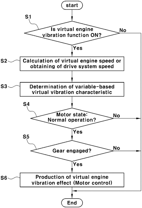
Electric vehicles have been gaining popularity in recent years, but many people are still hesitant to make the switch due to the lack of engine noise. Hyundai Motor Company has just announced a new method for generating virtual vibration effects of an internal combustion engine in electric vehicles. This revolutionary system collects driving variable information and uses it to determine a virtual internal combustion engine vibration characteristic that is then used to create a final motor torque command which controls the operation of the vehicle's driving motor according to this determined command. This innovative technology will allow drivers of electric vehicles to experience all the benefits associated with them while also being able to enjoy some of their favorite features from traditional engines - such as sound and feel. With this new development, Hyundai Motor Company continues its commitment towards making electric vehicles more accessible and enjoyable for everyone!
The patent describes a method of generating vibration in an electric vehicle. First, driving variable information is collected. Then, a virtual internal combustion engine vibration characteristic is determined on the basis of the collected driving variable information. Next, a vibration torque command is determined having the determined virtual engine vibration characteristic. Finally, a final motor torque command is calculated using the basic motor torque command and the determined vibration torque command. The vehicle driving motor is then controlled according to the final motor torque command.
US Patent 11565591
Ford Global Technologies, LLC
Charge up your ride with a deployable charging point assembly!
What is this invention?
Deployable charging points for vehicles
A charging point assembly was made
To provide a connection to be laid
It had a connecting part, movable between two
So that when in one of those spots it could do
The electrical power would connect with the car's system and so it'd stay fed!
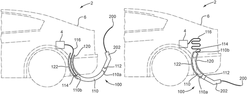
Drivers of electric vehicles now have a new way to charge their cars with the Deployable Charging Points for Vehicles, invented by Ford Global Technologies, LLC. This charging point assembly can be mounted on the vehicle and moved between two positions - one being a first position and the other being a second position. When in one or more predetermined positions between these two points, an electrical connection is established between the supply of power and the car's electrical system. This new technology makes it easier than ever before to keep your electric vehicle charged while on-the-go - no matter where you are! With this deployable charging point assembly, drivers of electric cars can rest assured that they will never run out of power when they need it most.
The patent describes a deployable charging point assembly for a vehicle. The assembly includes a connecting part that is movable between a first position and a second position, and is configured to establish an electrical connection between the supply of electrical power and an electrical system of the vehicle when the connecting part is in one or more predetermined positions between the first and second positions.
US Patent 11565600
HONDA MOTOR CO., LTD.
Electric Vehicle diagnostic device warns drivers of inaccurate degradation state estimates
What is this invention?
Diagnostic device, diagnostic system, diagnostic method, and diagnostic program
A diagnostic device (100) was made
To estimate battery degradation grade,
An index value it found
When accuracy went down,
The cause of the drop to be displayed.
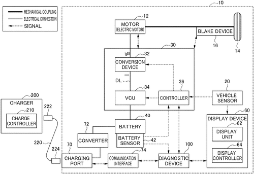
Honda Motor Co., Ltd. has developed a diagnostic device, system, method and program to help drivers better understand the condition of their electric vehicle's secondary battery. This device is able to estimate the degradation state of the battery and derive an index value indicating validity of data used for this estimation. It also notifies drivers when accuracy of an estimated value is determined to be low based on the index value, providing them with information as to why it’s decreased in accuracy. This advanced technology from Honda Motor Co., Ltd. will allow drivers to have greater insight into their electric vehicle’s performance and can help prevent incorrect information being given regarding the battery’s condition or performance levels. With this innovative technology, Honda Motor Co., Ltd. is setting a new standard for diagnostics in electric vehicles!
The diagnostic device (100) includes an estimation unit (301) that estimates a degradation state of the battery (40). The estimation unit (301) derives an index value indicating validity of data used for the estimation of the degradation state. The notification unit (303) notifies, when accuracy of an estimated value is determined to be low based on the index value, a cause of a decrease in the accuracy of the estimated value.
US Patent 11565606
Hyundai Motor Company
Control Low Voltage DC Converter of Fuel Cell Vehicle to Prevent Fuse
What is this invention?
System and method for controlling low voltage DC converter of fuel cell vehicle
A system and method were arranged
To control a low voltage DC converter
Though CAN communication timeout, or failure occurs
When output current is lessened by force
The fuel cell system will be done soon
Relay of the high voltage battery then open!
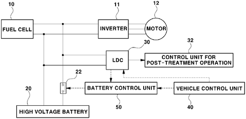
Hyundai Motor Company has just unveiled their newest invention - a system and method for controlling low voltage DC converters of fuel cell vehicles. This new system is designed to protect the high voltage battery from fusing in the event of a CAN communication timeout or failure, where the low voltage DC converter does not receive an off command from the vehicle control unit. The system works by detecting when the output current of the converter is lowered by at least a predetermined value, which indicates that post-treatment operations of the fuel cell system are complete. Once this happens, it will automatically turn off itself and open up a relay on the high voltage battery, thus preventing any potential damage due to fusing. This is yet another example of Hyundai's commitment to safety and innovation in automotive technology. With this latest invention, drivers can rest assured knowing that their vehicles are protected against unexpected power outages or failures - no matter where they're driving!
The system and method are arranged to control a low voltage DC converter of a fuel cell vehicle, in which, although a CAN communication timeout where the low voltage DC converter does not receive an off command from a vehicle control unit or a CAN communication failure occurs, when an output current of the low voltage DC converter is lowered by at least a predetermined value, the low voltage DC converter is turned off by itself. If post-treatment operation of the fuel cell system is completed before the low voltage DC converter is turned off, then relay of the high voltage battery will be opened.
US Patent 11565608
TOYOTA MOTOR ENGINEERING & MANUFACTURING NORTH AMERICA, INC.
Convert Your Vehicle Seat Into A Ladder Or Ramp!
What is this invention?
Vehicle seat convertible into vehicle access and loading tool
A seat that can be a ladder or ramp
It's back surface faces the ground when in camp
The bottom end is attached to cushion so sweet
When used as step it makes access complete
This locking member keeps it at an angle less than ninety degree.
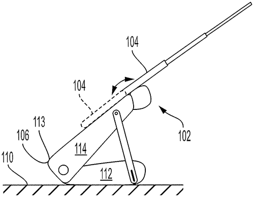
Have you ever wished that your car was more than just a mode of transportation? Well, now it can be with Toyota Motor Engineering & Manufacturing North America’s new invention: the Vehicle Seat Convertible into Vehicle Access and Loading Tool. This innovative seat transforms from a regular car seat to a ladder or ramp configuration in seconds, allowing drivers to access and load their vehicle with ease. The removable seat cushion has a back surface which faces the ground when converted into either the ladder or ramp configurations. The bottom end of the seat back is pivotally attached to the cushion and oriented towards the back end, while being lockable in place relative to the cushion at an angle equal to or less than ninety degrees with at least one locking member. Finally, there is also a ladder or ramp attached to the seat back which can be used for accessing and loading onto your vehicle once converted. This revolutionary invention will make it easier than ever before for drivers everywhere! No longer do you have worry about struggling up steep ramps - this tool does all of that work for you! So if you're looking for an easy way to access and load your vehicle without breaking your back in process, look no further than Toyota's Vehicle Seat Convertible into Vehicle Access and Loading Tool!
This document describes a removable vehicle seat that can be converted between a seat configuration and a ladder or ramp configuration. The seat may include a back surface that faces the ground when in the seat configuration, and a bottom end attached to the cushion. The bottom end may be oriented towards the back end, which allows it to be used as a step for accessing or loading the vehicle once converted. The seat also includes a locking member to keep it in place relative to the cushion at an angle less than ninety degrees.
US Patent 11565613
Ford GLobal Technologies, LLC
Vehicle automatically rotates or turns wheel based on state and condition
What is this invention?
Active wheel theft prevention
A vehicle with two sensors, one inside
That senses a state and the other outside
The computing device receives data from both
To control wheels when parked, that is its oath.
It initiates turning or rotating of wheel
If conditions are met while it remains still
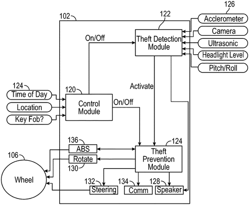
Ford Global Technologies, LLC has developed an innovative new feature to help prevent vehicle theft - Active Wheel Theft Prevention. This system utilizes sensors that detect a state of the vehicle and outside conditions, as well as a computing device to control rotation and turning of the wheels. While your car is parked, the computing device will automatically initiate rotating or turning of any wheel associated with certain conditions it detects from its sensors. This helps deter potential thieves who may be trying to steal your car by making it more difficult for them to move the wheels. Active Wheel Theft Prevention is just another way Ford Global Technologies, LLC is helping make our roads safer and more secure than ever before!
A vehicle includes a first sensor that senses a state of the vehicle and a second sensor that senses outside of the vehicle. A computing device is configured to receive signals from the sensors and to control rotating and turning of the wheels. While the vehicle is parked, the computing device determines according to a signal received from the sensors, that a condition is satisfied. The condition may be associated with a particular wheel. Based on determining that the condition is satisfied, and while the vehicle remains parked, the computing device initiates automatically rotating or turning (or both) of the particular wheel associated with the condition.
US Patent 11565655
Ford Global Technologies, LLC
Braking system keeps you safe - no more surprises
What is this invention?
Automatic brake pedal control
A braking system for a car
Had a controller that went far,
It adjusted the brake pedal,
To apply zero torque lethal,
For safe stopping from afar.
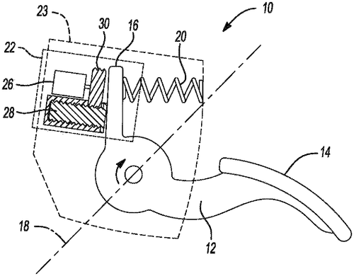
Ford Global Technologies, LLC has developed a revolutionary new brake pedal control system that will make driving safer and easier than ever before. This Automatic Brake Pedal Control system uses a controller to move the brake pedal to a predetermined position in response to automatic braking torque applied by the braking system. This means that when you need to stop your vehicle quickly and safely, the brakes will be automatically adjusted so you don't have to worry about manually adjusting them yourself. Furthermore, this controller can update itself so that it always corresponds with zero braking torque - meaning your car is always ready for an emergency stop without any manual adjustment on your part. With this technology from Ford Global Technologies, LLC, drivers everywhere can rest assured knowing their vehicles are prepared for anything!
The patent describes a braking system for a vehicle. The system includes a brake pedal and a controller. The controller may cause the brake pedal to move to a predetermined position responsive to automatic application of braking torque by the braking system. The controller may further implement an update such that the predetermined position corresponds to zero braking torque.
US Patent 11565667
Honda Motor Co., Ltd.
Hybrid Vehicle Control Apparatus Ensures Torque Converter Temperature is Equal to or Lower Than Predetermined Temperatures
What is this invention?
Hybrid vehicle control apparatus
A hybrid vehicle control apparatus made,
It had a torque converter and rotor grade,
Stator temperature detected too,
By an ECU that's true blue,
To make sure temps stayed at the right brigade.
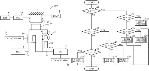
Honda Motor Co., Ltd. has just unveiled their new Hybrid Vehicle Control Apparatus, a revolutionary system that is designed to keep your hybrid vehicle running smoothly and efficiently. This apparatus includes a torque converter temperature detector, rotor temperature detector, stator temperature detector, and an electronic control unit with a microprocessor. The microprocessor is programmed to monitor the temperatures of each component in order to ensure they are all at optimal levels for maximum performance. It will also adjust engine speed, transmission settings, lockup clutch status, motor-generator functionality and stator cooling device accordingly so that the torque converter temperature stays below the first predetermined level while rotor and stator temperatures remain lower than their respective thresholds as well. With this advanced technology from Honda Motor Co., you can be sure that your hybrid vehicle is always performing at its peak!
The hybrid vehicle control apparatus includes a torque converter temperature detector, a rotor temperature detector, a stator temperature detector, and an electronic control unit. The torque converter temperature detector detects the torque converter temperature, the rotor temperature detector detects the rotor temperature, the stator temperature detector detects the stator temperature, and the electronic control unit controls an engine, a transmission, a lockup clutch, a motor-generator and a stator cooling device based on these three temperatures. If any of these temperatures is lower than a predetermined value then the microprocessor will cause those components to operate in order to maintain that condition.
US Patent 11565686
HONDA MOTOR CO., LTD.
Control Device Keeps Hybrid Vehicles From Overheating
What is this invention?
Control device and computer readable storage medium
A control device was quite a boon,
It could tell where the car should be soon.
The arrival judging unit would decide,
If the battery had enough juice inside.
To start up the engine and waste heat supply, it'll do!
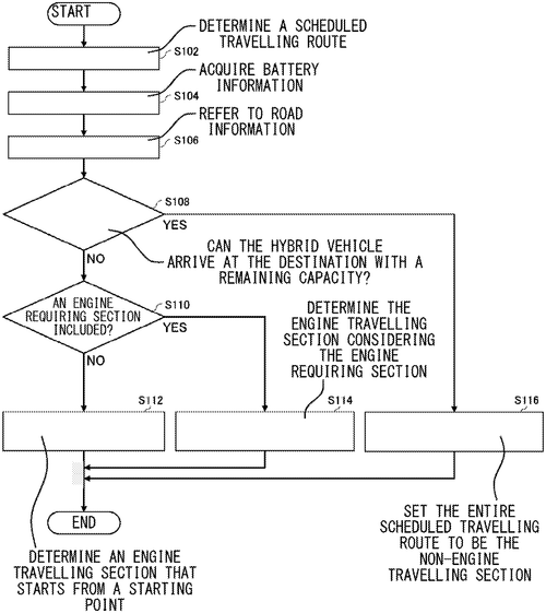
Honda Motor Company, Ltd. has just unveiled their latest innovation - a control device that helps hybrid vehicles optimize their performance and efficiency. This device includes a destination determining unit, an arrival judging unit, and a vehicle control unit. The destination determining unit determines the destination of the hybrid vehicle while the arrival judging unit judges whether or not it can arrive at its destination with its remaining battery capacity based on both its remaining capacity and temperature. Finally, the vehicle control unit will start up the engine when necessary to supply waste heat from it to the battery if needed in order for it to reach its desired location. This new technology is sure to revolutionize how we use hybrid vehicles by giving us more efficient ways of getting where we need to go! Not only does this save time but also energy which makes our journeys much greener than before! We are excited about Honda's newest invention and look forward to seeing what other innovations they come up with in future!
The control device includes a destination determining unit that determines a destination of the hybrid vehicle, a arrival judging unit that judges whether the hybrid vehicle can arrive at the destination with a remaining capacity of the battery based on the remaining capacity and a temperature of the battery, and a vehicle control unit that controls the hybrid vehicle to start the engine and supply the waste heat from the engine to the battery when the arrival judging unit judges that the hybrid vehicle cannot arrive at the destination.
US Patent 11565688
HYUNDAI MOTOR COMPANY
Autonomous Valet Parking Systems Enable Unmanned Vehicles to Park Themselves
What is this invention?
System, method, infrastructure, and vehicle for automated valet parking
A valet system was made for cars,
Where unmanned vehicles would travel far.
They'd communicate with the infrastructure so fine,
To determine their pickup spot in no time.
It's a feature that's truly sublime!
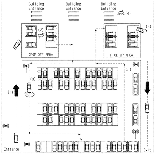
We're excited to review HYUNDAI MOTOR COMPANY's new automated valet parking system, method, infrastructure and vehicle. This innovative system makes it easier than ever before for drivers to find their designated parking spot without having to search around the lot or worry about someone stealing their space. By communicating with an infrastructure, the car is able to autonomously move into its designated spot and even return back to a pickup area when you’re ready. This technology has been designed with convenience in mind – no more wasted time searching for a free spot or waiting in long lines at crowded lots! Plus, this system eliminates any potential safety risks that come with leaving your car unattended while you try to find a place to park. The future of driving just got brighter thanks to HYUNDAI MOTOR COMPANY’s automated valet parking system!
This article describes an automated valet parking system, an automated valet parking method, and a vehicle having an automated valet parking feature. These systems enable unmanned vehicles to autonomously move to and park in designated spots by communicating with the infrastructure. The pickup area can be determined by the autonomous vehicle based on its current location and destination.
US Patent 11565691
Honda Motor Co., Ltd.
Get a Head Start on Distracted Driving Detection with Our Proximity Vehicle Data Estimation Method
What is this invention?
Systems and methods for distracted driving detection
A system for detecting distraction,
Will compare data with a prediction;
To flag those who drive,
With eyes off the road side,
It'll keep us from accidents' prevention.
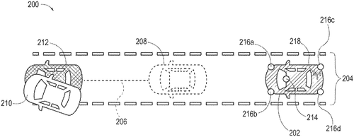
Distracted driving is a major issue on our roads, and Honda Motor Co., Ltd. has come up with an innovative solution to help make our roads safer. Their Systems and Methods for Distracted Driving Detection uses data from proximate vehicles to detect when another driver may be distracted or not paying attention to the road ahead. The system estimates one or more baselines for a predetermined future time for the proximate vehicle from the proximate vehicle data, then compares current kinematic data of that vehicle at that same time against those baselines in order to generate “distraction flags” associated with the driver. If these flags are detected, it can trigger one or more systems on your own car in order to ensure you stay safe while other drivers may not be as attentive. This new technology promises to revolutionize how we drive by helping us recognize potentially dangerous situations before they happen – making our roads safer than ever before!
This document describes systems and methods for detecting distracted driving. The system receives proximate vehicle data about a proximate vehicle and estimates one or more baselines for a predetermined future time from the proximate vehicle data. The system compares current kinematic data of the proximate vehicle data to the one or more baselines, and generates distraction flags associated with the proximate vehicle based on the comparison. The system controls one or more vehicle systems of the host vehicle based on the generated distraction flags.
US Patent 11565693
Hyundai Motor Company
Cruise control for hybrid vehicle: Estimating speed of preceding vehicle
What is this invention?
Cruise control method for hybrid vehicle
A hybrid car's cruise control,
Can detect the speed of a vehicle that's whole.
It sets an upper and lower limit,
For acceleration and deceleration to fit it,
The driver can rest while the car takes its toll!
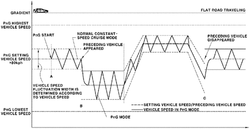
Hyundai Motor Company has just introduced a revolutionary new cruise control method for hybrid vehicles. This system utilizes information from a preceding vehicle detecting unit to accurately estimate the speed of the vehicle in front of you, and then sets an upper limit target vehicle speed and lower limit target vehicle speed based on this estimation. The driving source is then operated to alternately repeat acceleration (pulse phase) and deceleration (glide phase) between these two speeds - allowing you to maintain a safe distance from the car ahead while still keeping up with traffic. This all-new system makes it easier than ever before to keep your car running smoothly while also ensuring that you stay within the law when cruising down the highway!
The cruise control method for a hybrid vehicle includes detecting a preceding vehicle and estimating the speed of the preceding vehicle from the information input from a preceding vehicle detecting unit in the on state of a cruise mode and a PnG mode. An upper limit target vehicle speed and a lower limit target vehicle speed are determined from the estimated speed of the preceding vehicle. The driving source of the vehicle is operated to alternately repeat the acceleration (pulse phase) and deceleration (glide phase) of the vehicle between the determined upper limit target vehicle speed and lower limit target vehicle speed.
US Patent 11565694
HYUNDAI MOTOR COMPANY
Parking Control Method Prevents Curb Damage During Parking
What is this invention?
Vehicle equipped with electric motor and parking control method therefor
A parking control method to protect
Was devised in order to deflect
Collisions and curb runovers,
Which could cause a car lover's sorrows,
By creep torque imitation with an electric motor.

We are excited to review the latest innovation from Hyundai Motor Company - a vehicle equipped with an electric motor and parking control method. This revolutionary new technology is designed to prevent damage to both your vehicle and the parking curb when you park, thanks to its creep torque imitation by an electric motor. The system works by determining if a parking situation has occurred, then applying a modification coefficient to the creep torque until contact with something that applies reaction force in the direction of parking is detected. Once this happens, it variably controls the creep torque using a variable coefficient applied to the modified creep torque. This innovative new system from Hyundai Motor Company will make sure you never have any unwanted collisions or damages while backing into those tight spots again! Make sure your next car comes equipped with this amazing feature for maximum safety during your daily drives!
The present disclosure relates to a vehicle and a parking control method therefor which can prevent a parking curb or a driving system from being damaged during parking due to collision with the parking curb or running over the parking curb according to creep torque imitation by an electric motor in a vehicle equipped with the electric motor. A parking control method includes determining whether a parking situation occurs, applying a creep torque modification coefficient to a creep torque until contact with an object that applies a reaction force to a wheel in the parking direction is sensed to determine the modified creep torque upon determining the parking situation, and variably controlling the Creep Torque by applying a variable coefficient thereto. This allows for damage prevention during Parking due to Collision with The Parking Curb Or Running Over The Parking Curb According To Creep Torque Imitation By An Electric Motor In A Vehicle Equipped With The Electric Motor.
US Patent 11565697
HONDA MOTOR CO., LTD.
Requesting Occupant to Perform Pre-Defined Action Notification Provided in Vehicle
What is this invention?
Vehicle control system, vehicle control method, and vehicle control program
There once was a system so grand,
It provided an outputter to stand.
Based on the time of day,
The notification changed in its way,
And it was always emphasized by command!
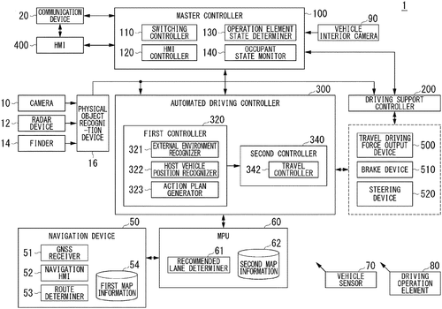
Honda Motor Co. Ltd has just released a revolutionary new vehicle control system that is sure to revolutionize the way we drive. This system includes an output controller, which provides a notification requesting occupants of the vehicle to perform a predetermined action when driving support is being executed by the controller. What makes this system unique is that it changes the form of the notification over time so that it becomes more and more emphasized as time passes from its start - making sure you don't miss any important instructions or warnings while you're on the road. This innovative new feature from Honda ensures that drivers are always aware of what they need to do in order to stay safe and abide by traffic laws, making our roads much safer for everyone involved. With this state-of-the-art technology, Honda continues to lead the pack when it comes to cutting edge automotive safety features!
The patent describes a system that provides an outputter to output notifications to occupants of the vehicle. The notification is changed based on time, and the outputter is configured to output the notification in an emphasized manner.
US Patent 11565713
Toyota Motor Engineering & Manufacturing North America, Inc.
Coordinating a Lane Change in an Autonomous Vehicle
What is this invention?
Autonomous vehicle, system, and method of operating an autonomous vehicle
There once was a vehicle so smart,
It could change lanes with an art.
The systems and methods it used,
Were designed to be fused,
To make sure the car drove safe from the start.
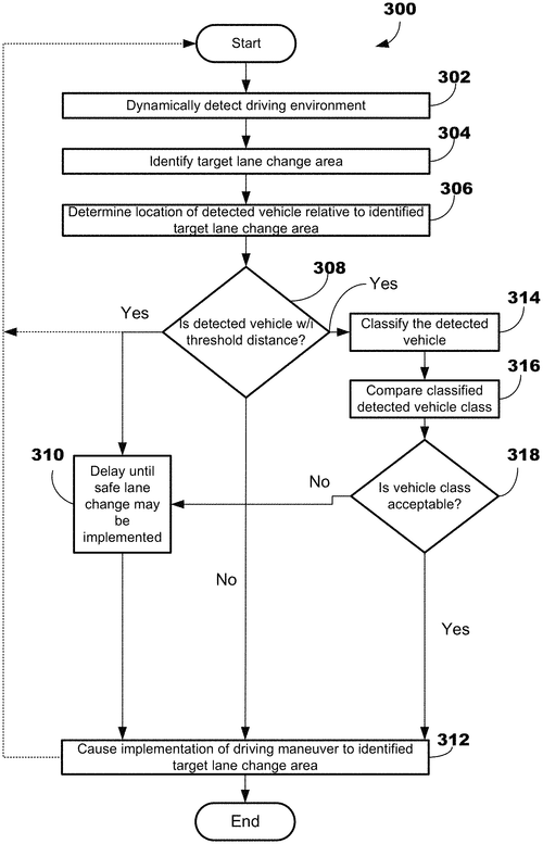
Today, Toyota Motor Engineering & Manufacturing North America, Inc. has announced a revolutionary new system for autonomous vehicles that will revolutionize the way we drive. This system is designed to coordinate lane changes in multi-lane roadways and take into consideration several operational safety factors such as the presence of other vehicles and the roadway design. This technology is sure to make driving safer than ever before by providing drivers with greater situational awareness and accuracy when making lane changes. With this system in place, drivers can be confident that their vehicle will always make safe decisions when navigating busy roads or highways. Toyota's Autonomous Vehicle System promises to revolutionize how we drive by allowing us to have more control over our safety on the road while still being able to enjoy all of the benefits of an autonomous vehicle. We look forward to seeing what else Toyota has in store for us!
The patent describes systems, methods, and computer program products to improve the situational competency of a vehicle when operating in autonomous mode, and/or the safe operation of a vehicle when operating in autonomous mode. These systems are designed to help coordinate a lane change from the first lane that the vehicle is currently occupying and a target lane change area in a second lane. This coordination takes into account several operational safety factors within the driving environment, including the presence of other vehicles in a third lane adjacent to the target lane area.
US Patent 11565720
Hyundai Motor Company
Autonomous Vehicle With Foldable Pedals Can Easily Switch to Manual Driving Mode
What is this invention?
Method of controlling switching to manual driving mode in autonomous vehicle equipped with foldable pedal device
There once was a car that could drive,
It switched to manual when safety's alive.
If the driver became lost or incapacitated,
This method would keep all of us elated!
For it prevents accidents from coming our way,
Making sure we're safe night and day.
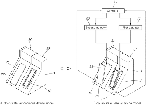
Hyundai Motor Company has recently developed a revolutionary new method for controlling the switch to manual driving mode in autonomous vehicles. This system is designed with foldable pedal devices that will allow drivers to quickly and safely transition from autonomous driving mode to manual driving mode. The process begins when a signal is generated indicating it’s time to switch from an autonomous driving mode to a manual one. The vehicle then checks safety conditions before determining if the pop-up positions of both the accelerator and brake pedals are normal. If they are, then the switch can be made without any further complications or delays. This new method ensures that switching between modes is as safe and efficient as possible, allowing drivers greater control over their vehicles while still keeping them protected from potential hazards on the road. With this technology, Hyundai Motor Company continues its commitment towards providing innovative solutions for safer roads everywhere!
This method allows autonomous vehicles to automatically switch to manual driving mode when certain safety conditions are met. This can prevent accidents from happening if the driver becomes incapacitated or lost control of the vehicle.
US Patent 11565725
Hyundai Motor Company
Dock Your Drone with This Unique Structure!
What is this invention?
Drone docking structure of autonomous vehicle and a method for delivery using the same
A drone docking structure was made,
To dock a drone and nothing more;
The coil housing had space,
For the motor to take its place,
And the cover opened when it was in store.
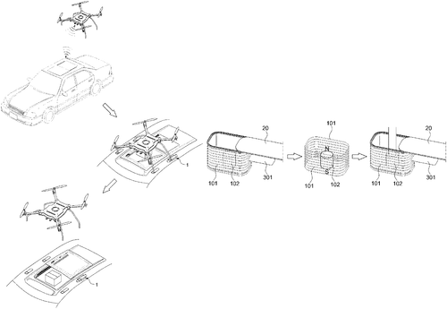
We live in a world of ever-evolving technology, and the Hyundai Motor Company is pushing the boundaries with their new drone docking structure for autonomous vehicles. This revolutionary system includes a coil housing with an enclosed space to dock a drone, as well as a motor housing installed on its side surface that contains a motor to actuate the docking cover. With this innovative system, you can easily transport goods from one place to another without having to worry about manually loading or unloading them! Not only does it make delivery more efficient than ever before, but it also keeps your vehicle safe and secure while traveling. The future of transportation just got brighter thanks to this incredible invention from Hyundai Motor Company!
The patent describes a drone docking structure for an autonomous vehicle, which includes a coil housing with space for docking a drone, and a docking cover that opens or closes according to whether the drone is docked. The motor housing is installed on the side surface of the coil housing and includes a motor that activates the docking cover.
US Patent 11565829
Toyota Motor Engineering & Manufacturing North America, Inc.
Securement system for rolling cart on ground
What is this invention?
Positional securement system for a rollable cart
A securement system for carts
Resides on a ground surface, not far apart.
It includes a first mechanism base,
Which defines a cavity to receive the rolling element in place.
Its blocking member adjusts with ease, so it never gets stuck and stays at peace!
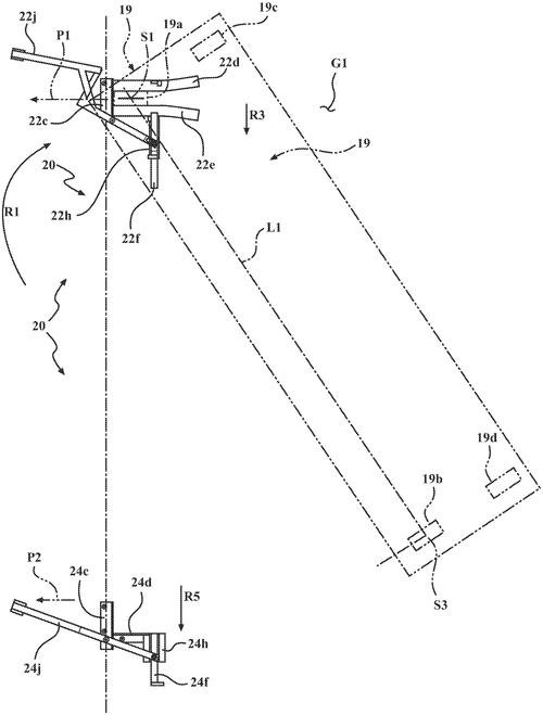
Toyota Motor Engineering & Manufacturing North America, Inc. has developed a revolutionary new securement system for rollable carts. This system is designed to prevent the cart from rolling away while it is resting on the ground surface, and can be easily adjusted to fit any size or shape of wheel. The securement system includes a first mechanism base that defines a cavity which receives the wheel of the cart while it’s in direct contact with the ground surface. Additionally, this mechanism includes a blocking member which can be adjusted to either block or open up a path for the wheel out of its cavity depending on your needs. This securement system provides an excellent solution for anyone who needs their rollable carts to stay put when not in use - whether you’re working outdoors or indoors, Toyota’s positional securement system will make sure your cart stays where it should at all times!
A securement system for restricting rolling of a rollable cart resides on a ground surface. The system includes a first mechanism including a first mechanism base defining a first cavity structured to receive the rolling element therein while the rolling element is in direct contact with the ground surface. The first mechanism blocking member is operably coupled to the first mechanism base and adjustable to a closing position in which it blocks the path of the rolling element out of the first cavity, and an opening position in which it does not block the path of the rolling element out of the first cavity.
US Patent 11565880
SEIKO EPSON CORPORATION
Feeder Keeps Objects Moving to Pick Them Up Easily
What is this invention?
Feeder and robot system
This feeder is quite a sight to see
It's got an object container unit, you'll agree
The vibrator then does its thing
And objects go flying in a zing!
All thanks to the patent of this machine.
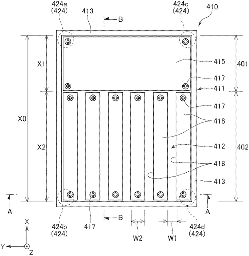
Epson Corporation has just released a revolutionary new feeder and robot system! This innovative system includes an object container unit with a first planar surface in which objects are thrown, as well as a groove portion with multiple grooves extending in one direction. Additionally, the vibrator unit applies vibration to the object container unit, allowing for movement of objects in one direction. This technology is perfect for those looking to streamline their robotic operations by increasing efficiency and accuracy when feeding objects into robots. With this cutting-edge system from Epson Corporation, you can be sure that your robotic operations will run smoothly and efficiently every time.
The feeder described in this patent includes an object container unit with a first planar portion including a first planar surface, and a groove portion extending from the first planar portion in a first direction. The vibrator unit applies vibration to the object container unit in a first vibration mode, which causes the objects thrown into the object container unit to move in the first direction.
US Patent 11565889