Most innovative companies for 12/27/2022 (new inventions)
Exciting new inventions from Hyundai Motor Company, Honda Motor Co., Ltd., Subaru Corporation, The Boeing Company And Ricoh Company, Ltd.
This is a weekly article summarizing a handful of inventions from the most innovative companies in the world. The summaries are created by an A.I. and proof-read by a human before publication. Attempts are made to ensure accuracy of the descriptions, but it is very much a work in progress. Each invention description is preceeded by a poem about the invention that is written by the A.I. I have found the limerick is actually quite good at explaining the invention in simple terms. Enjoy!
HYUNDAI MOTOR COMPANY
Lost Powder Trapped by Magnetic Force in Trap Device
What is this invention?
Trap device for powder coating apparatus
A trap device for powder coating
Will help keep your work from eroding
It captures the lost,
With a magnetic force,
So you'll have less mess when it's exploding!
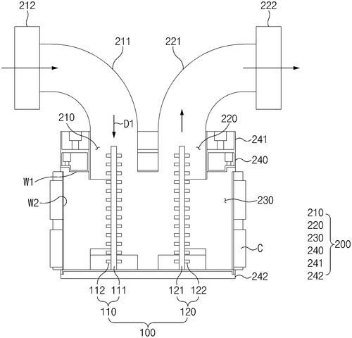
We are excited to introduce the Trap Device for Powder Coating Apparatus from Hyundai Motor Company. This device is designed to trap lost powder contained in exhaust gas, making it easier and more efficient than ever before to coat surfaces with a fine dusting of paint or other materials. The trap part of the device works by using a magnetic force to attract and hold onto the lost powder, allowing it to be collected and reused instead of wasted. Not only does this save on material costs, but it also helps reduce environmental waste as well! With its simple design and easy installation process, this trap device can help make your next coating project faster and more cost-effective than ever before.
The present disclosure relates to a trap device for a powder coating apparatus. The trap device includes a body part including an inlet through which exhaust gas containing lost powder is introduced, an outlet through which the exhaust gas is discharged, and an interior space in communication with the inlet and the outlet and a trap part that is located in the interior space of the body part and that traps the lost powder contained in the exhaust gas by a magnetic force.The trap device may be used with a powder coating apparatus to remove lost powder from the exhaust gas.
US Patent 11534772
Honda Motor Co., Ltd.
Clean Paint Sprayer with Rotating Atomization Head
What is this invention?
Method for cleaning paint spray gun
A method for cleaning a paint spray gun
Includes an atomization head that rotates and spun,
With an outer tube to cover the outside,
And a cleaning solution applied with pride,
Rotating the head creates a flow between them done.
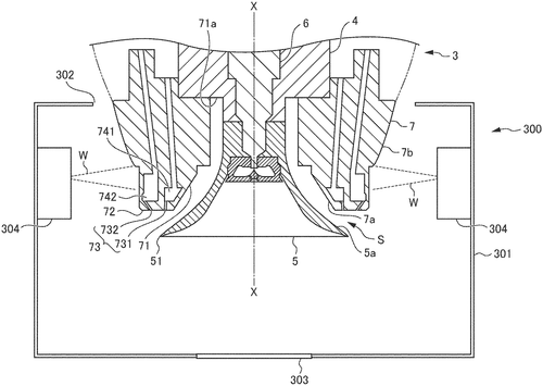
Honda Motor Co., Ltd. has come up with a revolutionary way to clean paint spray guns in an efficient and cost effective manner. Their method involves applying a cleaning solution to the external face of the outer circumferential tube, then generating a rotational flow between the rotating atomization head and the outer circumferential tube by rotating it. This allows for the cleaning solution to penetrate between these two parts, effectively cleaning both their internal and external faces while using only a small amount of cleaning solution. This new method from Honda is perfect for those who need to keep their equipment clean without having to use large amounts of expensive chemicals or spend too much time on maintenance tasks. Now you can get your job done quickly and efficiently thanks to this innovative invention!
A method for cleaning a paint spray gun includes a rotating atomization head to apply a coating material while rotating and an outer circumferential tube to cover the exterior of the rotating atomization head. The method also includes a cleaning solution application step for applying a cleaning solution to the external face of the outer circumferential tube, and a rotating atomization head rotation step for generating a rotational flow between the rotating atomization head and the outer circumferential tube by rotating the rotating atomization head. The cleaning solution flowing down the external face of the outer circumficial tube applied in the cleaning solution application step penetrates between the rotating atomization head and the outer circumferential tube by way of the rotational flow. Such method uses a small amount of cleaning solution for cleaning external and internal faces of the outer circumferential tube and
US Patent 11534789
SUBARU CORPORATION
Laser Peening Processing Method Results in Precise, Durable Parts
What is this invention?
Laser peening processing apparatus
A laser peening processing apparatus
Had a laser oscillator and a lens
It irradiated with light,
In the air not in flight,
To make products with no mess or stress.
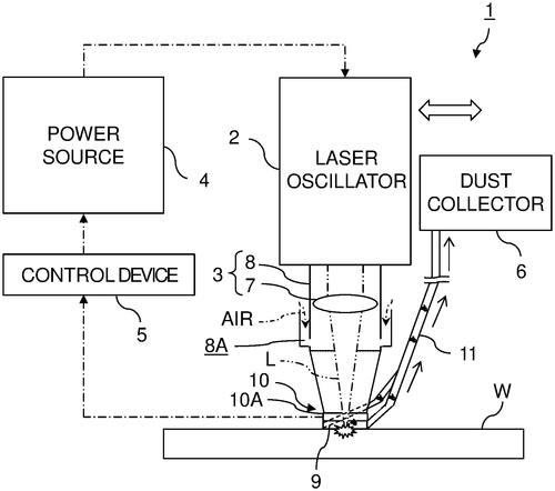
We are excited to announce the newest innovation from SUBARU CORPORATION: a Laser Peening Processing Apparatus. This apparatus includes a laser oscillator and an irradiation system that can condense laser light with a lens, allowing for precise laser peening processing of workpieces without interposed liquid. This new technology has many advantages over traditional methods of peening, including increased accuracy and precision as well as improved safety due to its lack of liquid components. Additionally, this apparatus is perfect for on-the-go projects due to its portability - meaning you can take it wherever you need to go! Overall, we think this new invention from SUBARU CORPORATION will revolutionize the way people approach peening projects in the future - so make sure you check it out today!
A laser peening processing apparatus includes a laser oscillator and an irradiation system. The laser oscillator oscillates a laser light. The irradiation system condenses the laser light with a lens and irradiates a workpiece with the condensed laser light. The irradiation system irradiates the workpiece with the laser light in a state where the workpiece has been exposed in an atmosphere without interposed liquid. Furthermore, according to one implementation, a method of producing a product or semi-product by Laser Peening Processing using this apparatus is also described.
US Patent 11534866
THE BOEING COMPANY
Drill guide for chucked hand-held drill: Keep your bits safe and in good shape with this easy-to-use tool!
What is this invention?
Drill guide for hand-held drill
A drill guide for a bit, of a chucked hand-held drill,
Is disclosed with much zeal and skill.
The mount will couple to the non-rotating part,
And the telescoping guard is quite smart.
The guide foot helps it all come together so neat; A great invention that's hard to beat!

Do-it-yourselfers, rejoice! The Boeing Company has just introduced an amazing new drill guide for hand-held drills. This revolutionary tool is designed to make drilling easier and safer than ever before. It features a mount that couples to the non-rotating portion of your chucked hand-held drill, as well as a coupler that creates a chuck access window so you can easily insert your chuck key. Additionally, it comes with a telescoping guard that extends from the coupler and retracts when not in use, and also includes a guide foot which ensures the drill bit remains securely enshrouded during operation. This advanced drill guide makes drilling more efficient and less dangerous - perfect for those who love DIY projects but don’t want to risk injury or damage their tools. Get yours today from The Boeing Company and revolutionize the way you do home improvement!
A drill guide for a drill bit of a chucked hand-held drill is disclosed. The drill guide includes a mount, a coupler, a telescoping guard, and a guide foot. The mount is configured to couple to a non-rotating portion of the chucked hand-held drill. The coupler extends from the mount and forms a chuck access window aligned with the chuck when the mount is coupled to the non-rotating portion of the chucked hand-held drill thereby allowing a chuck key to interface with the chuck. The telescoping guard extends from the coupler and is configured to telescope into an extended position from an retracted position. The guide foot is coupled to the telescoping guard such that the drill guide enshrouds the Drill Bit when Telescoping Guard in Extended Position and Drill Bit Passes Through Guide Foot When Telescoping Guard Is In Retracted Position
US Patent 11534877
The Boeing Company
Robots Drill Holes Faster and Easier Than Human Hands
What is this invention?
End effector assemblies for drilling a plurality of spaced-apart holes in a part, robots including the end effector assemblies, and associated methods
There was a part with holes to drill
The force application structure had quite the skill
To transition between states, and extend in and out
So precise placement of holes was no doubt.
The end effector assemblies were just right,
To make sure drilling went off without a fight!
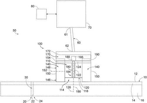
The Boeing Company has just unveiled a revolutionary new technology that is set to revolutionize the way we drill holes in parts. This new end effector assembly uses two force application structures and an end effector to precisely and accurately drill multiple spaced-apart holes in parts with ease. The first force application structure applies a first force to the surface of the part, while the second continuously applies a second force as the end effector moves from one predetermined location to another. Furthermore, this system can be used on robots for even greater accuracy and efficiency! This groundbreaking invention will make drilling easier than ever before, saving time and money while increasing productivity across many industries. We are excited to see how this technology will be implemented in various applications around the world!
The end effector assemblies described herein are useful for drilling a plurality of spaced-apart holes in a part. The first force application structure is configured to apply a first force to the surface of the part, while the end effector is configured to selectively transition the first force application structure between a retracted state and an extended state and to selectively extend a drill bit into the part and subsequently retract the drill bit from the part. The second force application structure is configured to continuously apply a second force to the surface of the part while the first force application structure is in either of these states, allowing for precise hole placement.
US Patent 11534921
RICOH COMPANY, LTD.
Robot arm shuts down when worker steps on sensor
What is this invention?
Emergency stop pressure sensor, safety device, and safety system
A worker who walks in the range
Of a robot arm, must not be strange
For when contact is made
The power will fade
Thanks to emergency stop pressure sensors installed on each side of the frame.
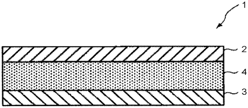
RICOH COMPANY, LTD. has developed a revolutionary safety system for assembly robots that uses emergency stop pressure sensors to instantly shut down power transmission if a worker accidentally walks into the robot’s swing range. This system is designed to detect contact between an intermediate layer of rubber or rubber composition and the contacted body (the worker), generating power upon deformation caused by this contact. To ensure maximum protection, one side of the intermediate layer in a laminate direction undergoes surface modification treatment and/or inactivation treatment, allowing both sides of the layer to have different degrees of deformation when exposed to force. This new technology from RICOH COMPANY, LTD. is sure to revolutionize how we use assembly robots safely in industrial settings. By providing workers with immediate protection against accidental collisions with robotic arms, this innovative safety system will help keep everyone safe on the job site - no matter what kind of work they are doing!
Emergency stop pressure sensors are installed on both side surfaces of a movable link of a robot arm of an assembly robot. When a worker unintentionally walks in a swing range of the robot arm and contacts the emergency stop pressure sensor, a detection signal is transmitted to a control unit which shuts power transmission to a driving source swinging the robot arm. The emergency stop pressure sensor has a first electrode and second electrode constituting a pair of electrodes and an intermediate layer formed of rubber or rubber composition, which is disposed between the pair of electrodes, the intermediate layer generating power upon deformation caused by contact with a contacted body (the worker). A side of the intermediate layer in a laminate direction undergoes surface modification treatment and/or inactivation treatment. With this treatment, the one side and other side of the intermediate layer have different degrees of deformation to generate same deformation adding force.
US Patent 11534929
THE BOEING COMPANY
Tool Forms Microscopic Features on Film in Seconds
What is this invention?
Methods and apparatus for forming microscopic features on a film layer
A tool with a patterned outer face
Was used to form on a film layer trace
It heated the plastic,
And it gave it elastic,
To make features that were quite small in space.
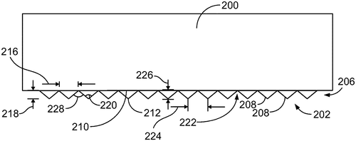
We are excited to announce the latest invention from THE BOEING COMPANY – methods and apparatus for forming microscopic features on a film layer. This revolutionary new tool allows you to form intricate shapes and patterns onto a thermoplastic film that is applied to a surface of a structure. By using friction between the outer surface of the tool and the thermoplastic film, it is able to generate enough heat via rotation at an appropriate speed to make the thermoplastic malleable so that it can be formed into any desired shape or pattern. This invention makes creating detailed designs easier than ever before, allowing you to quickly create complex shapes without having to use more traditional processes such as cutting or etching. With this technology, you can now easily add intricate details onto plastic films with ease - perfect for any creative project!
The apparatus for forming microscopic features on a film layer includes a tool having an outer surface defining a first microscopic pattern. The outer surface of the tool to engage a thermoplastic film applied to a surface of a structure. The outer surface is structured to frictionally engage the thermoplastic film and rotate relative to the thermoplastic film with a rotational speed that is sufficient to generate heat via friction between the outer surface and the thermoplastic film to heat the thermoplastic film to malleability. The second microscopic pattern in the thermoplastic film is formed as a result of this heating process.
US Patent 11534957
The Boeing Company
Construction System Wound Tubular Braiding Constructs Composite Structures
What is this invention?
Composite structures constructed of wound tubular braiding
There was a system that had three,
A braiding machine, winding tool and forming machine you see.
The composite structure they made
Was built with wound tubular braid
Of unidirectional tape so it could be biaxial or triaxial in grade!
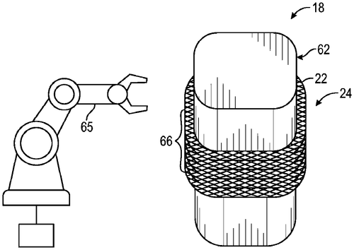
The Boeing Company has invented a revolutionary new way to construct composite structures - the wound tubular braiding system. This system includes a braiding machine, winding tool and forming machine that are used together to create strong, lightweight composite structures out of unidirectional tape. The biaxial or triaxial tubular braid is formed into a tube-like shape with the help of these machines, making it perfect for applications where strength and weight are important factors. With this invention, Boeing has made creating high-performance composites easier than ever before!
The system described in this text includes a braiding machine, a winding tool, and a forming machine. The composite structure is constructed of a wound tubular braiding. The wound tubular braiding is constructed of a biaxial or triaxial tubular braid of unidirectional tape.
US Patent 11534986
Ricoh Company, Ltd.
A Liquid Ejection Apparatus That Includes A Plurality Of Liquid Ejection Head Units Is Provided That Are Configured To Eject Liquid Onto A Conveyed Ob
What is this invention?
Liquid ejection apparatus, liquid ejection system, and liquid ejection method
A liquid ejection apparatus, that's true
It has a detection unit for view
The control unit will then adjust
Liquid ejecting, no fuss
To the conveyed object it'll accrue
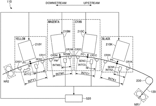
Ricoh Company, Ltd. has just unveiled their latest innovation: the Liquid Ejection Apparatus! This revolutionary system is designed to make liquid ejection easier and more efficient than ever before. The apparatus includes a plurality of liquid ejection head units that are configured to eject liquid onto a conveyed object being conveyed, as well as a detection unit and control unit for each head unit. The detection unit outputs information on the position, speed, and amount of movement of the conveyed object in relation to its conveying direction while the control unit uses this data to time when each head should eject its respective liquid. This new technology will greatly reduce waste by allowing users to accurately target their liquids with precision timing - making it perfect for any application where accuracy is key! So if you're looking for an easy way to get your liquids exactly where they need to be without wasting materials or time - look no further than Ricoh's Liquid Ejection Apparatus!
The liquid ejection apparatus includes a plurality of liquid ejection head units that are each configured to eject liquid onto a conveyed object being conveyed. The detection unit is provided with respect to each of the plurality of liquid ejection head units and is configured to output a detection result indicating at least one of a position, a moving speed, and an amount of movement of the conveyed object with respect to the conveying direction of the conveyed object. The control unit is configured to control each of the plurality of liquid ejection head units among the plurality of liquid ejection head units to eject liquid at a timing based on the plurality of detection results from the detection unit.
US Patent 11535031
RICOH COMPANY, LTD.
A New Liquid Discharge Apparatus That Allows for Precise Control of Pressure
What is this invention?
Liquid discharge apparatus and head drive control device
A liquid discharge head and some wiring
Were configured to do a lot of exciting
The waveform would vary,
With a deselection signal so wary,
For this apparatus was quite inviting!
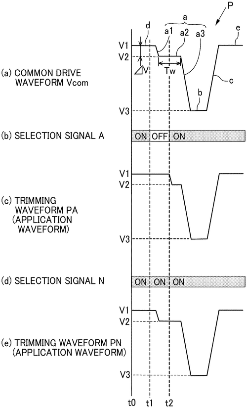
RICOH COMPANY, LTD. is proud to introduce its new Liquid Discharge Apparatus and Head Drive Control Device. This system has been designed to make liquid discharge easier than ever before by combining a nozzle with circuitry that generates a common drive waveform and selects the appropriate waveform portion for each application. The drive pulse includes an expansion waveform element for expanding a pressure chamber of the liquid discharge head and a holding waveform element for maintaining this state, while the selection signal deselects any preceding parts of the waveform as needed. This groundbreaking apparatus allows users to easily adjust their settings based on their particular needs, making it perfect for any situation where precise liquid discharge is required. Whether you’re in need of an efficient way to dispense liquids or just want more control over your process, RICOH COMPANY’s Liquid Discharge Apparatus and Head Drive Control Device are sure to provide you with exactly what you need!
The patent describes a liquid discharge apparatus that includes a liquid discharge head and circuitry. The liquid discharge head includes a nozzle to discharge liquid and the circuitry is configured to: generate and output a common drive waveform including a drive pulse for discharging liquid from the nozzle of the liquid discharge head; select a waveform portion of the drive pulse to be applied to a pressure generating element of the Liquid Discharge Head; and output a selection signal for designating the waveform portion selected. The drive pulse includes at least an expansion waveform element for expanding a pressure chamber of the Liquid Discharge Head and a holding waveform element for holding state expanded by the expansion waveform element. The selection signal includes deselection signal for deselecting at least part of one Waveform portion preceding expansion Wave form Element having, as terminal, state held by Holding Wave Form Element.
US Patent 11535032
HONDA MOTOR CO., LTD.
Non-Pneumatic Tires Provide Greater Traction
What is this invention?
Non-pneumatic tire
A tire with a tread that can cling
Had a wheel, spokes and disc ring
The rim was thinned out
So it had no doubt
It could grip the ground like an eagle's wing
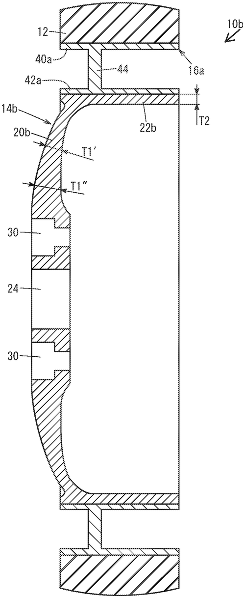
Honda Motor Co. Ltd. has recently unveiled their revolutionary non-pneumatic tire, designed to provide superior performance and durability for vehicles of all types. This innovative new tire is composed of a tread ring, wheel arranged radially inside the tread ring, and spokes interposed between them - but what sets this tire apart from traditional models is the unique design of its wheel component. The disc part is linked directly to the vehicle shaft, while the rim part is connected on the inner side to the disc part and joined on the outer side with spokes - creating an average thickness (T1) that's greater than that of its rim part (T2). This advanced engineering provides drivers with improved handling capabilities along with increased stability when cornering or driving over rough terrain - making it perfect for everyday use as well as off-road adventures. With Honda's non-pneumatic tires, you can enjoy a smoother ride no matter where your journey takes you!
The patent describes a non-pneumatic tire with a tread ring, wheel, and spokes. The average thickness of the disc part is greater than the average thickness of the rim part. This allows for better grip on the ground.
US Patent 11535053
Hyundai Motor Company
Independent Suspension System Adds Comfort and Control
What is this invention?
Independent suspension system
A suspension system independent
Includes a steering unit that's bent
A shock absorber too,
Engaged with the wheel to view,
The ground clearance adjustment is spent.
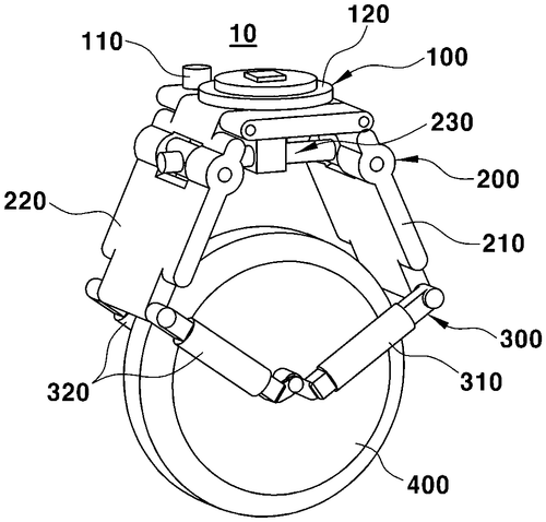
We are proud to introduce the revolutionary new independent suspension system from Hyundai Motor Company. This innovative system features a steering unit that can be adjusted to change the angle of a wheel, two shock absorbers arranged on opposite sides of the wheel, and a link unit between them which can vary the distance between the wheel and steering unit. The link unit also includes an adjustable ground clearance adjustment feature so you can quickly adjust your ride height with ease. This groundbreaking technology provides superior handling and stability while driving over rough terrain or in inclement weather conditions. With this advanced suspension system, drivers will experience greater control and comfort when maneuvering their vehicles - no matter what kind of road they're on! So if you're looking for an improved driving experience that won't break your budget, look no further than Hyundai's independent suspension system!
An independent suspension system includes a steering unit that's configured to be controlled to adjust the steering angle of a wheel, a shock absorber engaged with the wheel in order to absorb external impacts applied to the wheel and including first and second shock absorbers, each of the first shock absorber and the second shock absorber arranged in a forward-rearward direction on opposite side surfaces of the wheel, respectively. The link unit is disposed between the shock absorber and the steering unit in order to vary the distance between the wheel and the steering unit. The ground clearance adjustment unit is engaged with the first and second upper arms and is configured to vary the distance therebetween while varying the distance between the wheel andthe steering unit at same time.
US Patent 11535075
SUBARU CORPORATION
Inspections with Thermal Camera and Processor Ensures Equipment is Running Correctly
What is this invention?
Inspection system
A thermal camera and inspection processor
Were mounted on a vehicle for the inspector
Once it was started,
The heat transfer part's charted
And imaging state can be modified to reflector
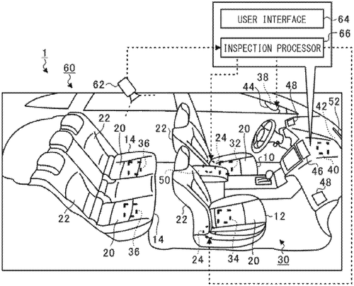
We are excited to introduce the latest innovation from SUBARU CORPORATION: an innovative inspection system. This system includes a thermal camera and an inspection processor, both of which can be mounted on vehicles. The thermal camera is used to image the heat transfer part of heating and cooling equipment, while the inspection processor will execute operation check inspections to determine if the equipment is operating normally. Furthermore, this system also has a modification process that enables the heat transfer part to be imaged by the thermal camera more effectively. This new invention from SUBARU CORPORATION makes it easier than ever before for technicians to inspect and maintain heating and cooling systems in vehicles quickly and accurately - no matter where they are located! By streamlining these processes, we can ensure that all vehicles remain safe and efficient for years to come.
An inspection system includes a thermal camera and an inspection processor. The thermal camera is mountable on a vehicle and configured to perform imaging of a heat transfer part of heating and cooling equipment mounted on the vehicle. The inspection processor is configured to execute, after causing the heating and cooling equipment to start operation, operation check inspection of determining whether the heating and cooling equipment normally operates on the basis of an image of the heat transfer part obtained by the imaging by the thermal camera, and to, in executing the operation check inspection, perform a modification process of modifying an imaging state of the thermal camera to enable the heat transfer part to be imaged by the thermal camera.An inspection system may include means for modifying an imaging state of a thermal camera in order to enable imaging of a heat transfer part located on or near one or more components operated by or associated with said heating and cooling equipment.
US Patent 11535083
HONDA MOTOR CO., LTD.
Second Battery Output Limitation Ensures Safe Operation
What is this invention?
Power supply system
A power circuit to supply
Connects two batteries, so nigh
The ECU will limit
The output of the second bit
So that travel's not too high.
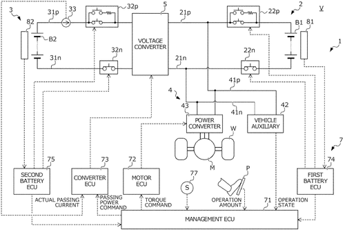
Honda Motor Co. Ltd. has just unveiled a revolutionary power supply system that promises to revolutionize the way we use batteries in our vehicles. This new system connects two batteries to a drive motor and is managed by an ECU (Electronic Control Unit) which controls the transfer of power between them. The ECU limits the output power of one battery, while allowing for combined output travel when needed - so you can get more out of your vehicle even if one battery runs low on charge! Additionally, it sets different upper limits depending on how much charge remains in each battery, ensuring maximum efficiency and safety at all times. This advanced technology from Honda provides an efficient and reliable way to ensure that your vehicle never runs out of juice - no matter where you are or what kind of terrain you're driving through! With its intuitive design and clever features, this new power supply system is sure to be a game changer for drivers everywhere!
The power supply system includes a power circuit which connects first and second batteries with a drive motor. The management ECU limits the output power of the second battery to no more than a second output upper limit, during combined output travel which drives the drive motor by way of the combined output of the first and second batteries. In addition, the management ECU sets the second output upper limit to a range extending upper limit which is smaller than the second maximum output, in the case of the first SOC being less than the remaining amount warning threshold.
US Patent 11535106
SUBARU CORPORATION
Vehicle Uses Pre-Charge to Boost Electric Power Transmission
What is this invention?
Vehicle
A vehicle control system so wise,
It uses pre-charge processing to rise.
When the power acquirer is ready to use,
The controller switches on with a fuse.
DC mode it will go for improved transmission of juice!
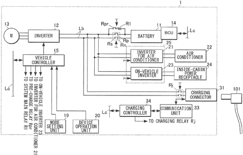
We are proud to announce the latest innovation from Subaru Corporation - a revolutionary new vehicle with an advanced electric power transmission system. This cutting-edge technology allows for efficient and safe transfer of electricity through the car's power line, all controlled by a sophisticated controller. The controller executes pre-charge processing on request for operation of the power supply unit, raising voltage in the process. It then causes a transition of mode to direct transmission mode, allowing electric power acquired by the electric power acquirer to be transmitted directly to the power supply unit. This breakthrough in automotive technology is sure to revolutionize how we drive and use our vehicles. With its powerful yet efficient design, it will make your driving experience smoother than ever before!
This article discusses a vehicle control system that uses pre-charge processing to switch the power line from an AC mode to a DC mode, in order to improve electric power transmission. This process is intended to optimize the charging of the battery, and can be performed when the electric power acquirer (e.g., a charger) is available for use. The controller switches the pre-charge relay on in response to a request for operation from the power supply unit, and then causes the transition of electric power transmission from AC to DC.
US Patent 11535118
HYUNDAI MOTOR COMPANY
Keep your car from sagging with this new seat support!
What is this invention?
Vehicle seat support assembly
A vehicle seat support assembly,
Includes a front link and bracket so classy.
The link is pivotally coupled,
So sagging's inhibited by the upper rail buffed.
For comfort in driving it will not be surpassed!
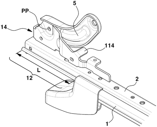
Hyundai Motor Company has recently unveiled their new Vehicle Seat Support Assembly. This innovative product is designed to help keep your vehicle seat in the best condition possible, no matter how long you’ve been driving. The assembly includes a front link and a front link bracket that are coupled to an upper rail of the vehicle seat. The sagging support portion of the bracket helps inhibit sagging of the front link towards the upper rail for added stability and comfort while driving. With this assembly, you can rest assured that your car's seating will remain comfortable and supportive throughout any journey!
The vehicle seat support assembly includes a front link and a front link bracket. The front link is pivotally coupled to the front link bracket. The sagging support portion of the front link bracket inhibits sagging of the front link toward the upper rail.
US Patent 11535128
Hyundai Motor Company
An apparatus, method, and vehicle for providing a braking level of a forward vehicle - Easy to use!
What is this invention?
Apparatus, method, and vehicle for providing braking level of forward vehicle
A braking level of a car
Can be determined from afar
By the apparatus, method, and vehicle
With relative acceleration they delve
To provide it to the driver so they don't mar.
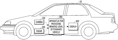
Hyundai Motor Company has developed an innovative new system that can help drivers better understand the braking level of a forward vehicle. This apparatus, method, and vehicle for providing a braking level of a forward vehicle uses an image recognition device to recognize brake lamp positions based on an image and relative acceleration of the forward vehicle. It also includes a braking determining device to determine whether or not braking is occurring, as well as a braking level determining device to quantify the degree of braking into a specific level. Finally, it features a braking level image providing device which presents this information in an easy-to-understand visual format. This breakthrough from Hyundai Motor Company will make driving safer by allowing drivers to quickly assess the situation ahead and adjust their speed accordingly. Now you'll always know when someone else is slowing down so you can react in time!
The apparatus, method, and vehicle described herein may determine a braking level of a forward vehicle. The braking level may be determined based on the relative acceleration of the forward vehicle. The apparatus, method, and vehicle may provide the braking level to a driver.
US Patent 11535153
THE BOEING COMPANY
Avoiding Collisions with precision
What is this invention?
Systems and methods for reducing a severity of a collision
There once was a car that could see,
It used systems to avoid collisions with glee.
The vehicle took actions so swift,
To protect itself and its gift,
For it knew the damage would be too much for me!
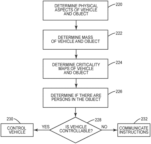
Staying safe on the roads is always a top priority, and now THE BOEING COMPANY has developed systems and methods to reduce the severity of collisions. This new system uses one or more inputs to determine when an impending collision is likely, then takes corrective actions to avoid it or minimize its damage. These systems can be used at both the vehicle level with data available from a control unit in the vehicle, as well as at a system level that controls multiple vehicles or objects. This technology could revolutionize safety on our roads by reducing the amount of accidents caused by human error. It also has potential applications for other industries where avoiding collisions between objects is important, such as aviation and maritime transportation. With this new system from THE BOEING COMPANY, we can look forward to safer journeys ahead!
The patent describes systems and methods for collision avoidance in vehicles. Collision avoidance is performed by taking corrective actions to avoid a collision or reduce the damage caused by a collision. The corrective actions can be performed at the vehicle level, but may also be performed at a system level that controls one or more other vehicles or objects.
US Patent 11535245
HYUNDAI MOTOR COMPANY
New Device Predicts Movement of Vehicle's User
What is this invention?
Apparatus and method for predicting movement of user of vehicle
A device that can predict with ease,
The movement of a driver in his vehicle.
An acceleration sensor to detect,
A braking controller to protect,
And steering controller for the wheel.
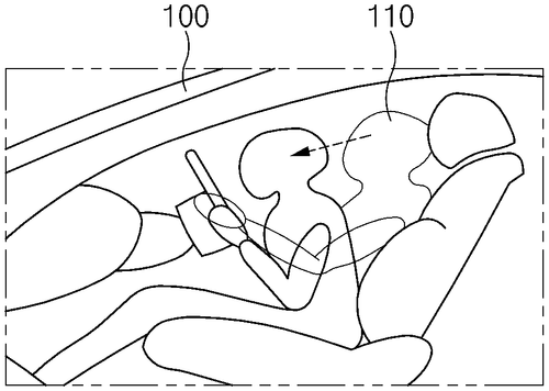
Hyundai Motor Company has just unveiled a revolutionary new apparatus and method for predicting movement of vehicle users. This incredible technology uses an acceleration sensor, braking controller, steering controller, and control circuit to monitor the operation of the braking controller and predict how the user will move based on longitudinal acceleration sensed by the sensor as well as a predetermined parameter. This groundbreaking invention from Hyundai is set to revolutionize safety in vehicles - allowing drivers to anticipate potential hazards before they happen. The system can detect when brakes are applied, then use this data along with other parameters such as speed and direction of travel to accurately predict what type of movement the driver or passenger may make next. By anticipating these movements ahead of time, drivers can be better prepared for any unexpected events that arise while on the road. We're excited to see how this amazing innovation from Hyundai could help improve safety standards in automobiles all around the world!
The patent describes an apparatus that is used to predict movement of a user of a vehicle. The apparatus includes an acceleration sensor that senses an acceleration of the vehicle, a braking controller that automatically controls a deceleration of the vehicle, and a steering controller that automatically controls a direction of the vehicle. The control circuit monitors an operation of the braking controller and predicts a movement of the user based on the longitudinal acceleration of the vehicle sensed by the acceleration sensor and a first predetermined parameter when braking is detected.
US Patent 11535263
Hyundai Motor Company
Driver-Enabled Vehicles: A Step Toward Safer Driving
What is this invention?
Vehicle and control method thereof
A driver had a car so clever,
It could detect his gestures ever.
For voice commands it was wise,
To manipulate the device,
And make driving much more effortless than ever!
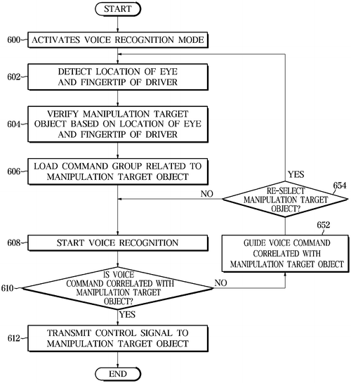
Driving has just gotten a whole lot easier with the new Vehicle and Control Method Thereof from Hyundai Motor Company. This revolutionary system allows you to control your vehicle through both gestures and voice commands - meaning you can now operate your car without ever having to take your hands off the wheel! With its gesture detector, this system detects any motion made by the driver to designate a manipulation target object, while its voice recognizer recognizes any voice command given by the driver in order to operate that same target object. On top of that, it also sends out a control signal corresponding to each command so as to make sure that everything runs smoothly. All in all, this is an amazing invention that will make driving safer and more efficient than ever before!
The patent describes a vehicle that includes a gesture detector and voice recognizer. The gesture detector detects a gesture of the driver to designate a manipulation target object, and the voice recognizer recognizes a voice command generated by the driver to operate the designated manipulation target object. The controller is configured to transmit a control signal corresponding to the voice command to the manipulation target object, and to operate the manipulation target object to perform an operation corresponding to the voice command.
US Patent 11535268
HYUNDAI MOTOR COMPANY
A New Way to Make a Rack Bar: Carbon Steel with Less Phosphorus
What is this invention?
Carbon steel for a rack bar and a method for manufacturing the same
A rack bar made of carbon steel
Was a product that had quite a feel
It contained C, Si and Mn
P and S in the mix too
Plus chrome, boron and iron as well

HYUNDAI MOTOR COMPANY has just unveiled a revolutionary new carbon steel for rack bars that is sure to revolutionize the industry. This steel contains 0.50 to 0.55% by weight of carbon (C), 0.15 to 0.35% by weight of silicon (Si), 0.75 to 0.95% by weight of manganese (Mn), and other elements in precise amounts, making it one of the most advanced steels available today for this purpose. Additionally, HYUNDAI MOTOR COMPANY's method for manufacturing these rack bars includes quenching, tempering, drawing the carbon steel and warm forging the drawn carbon steel - all processes which ensure maximum durability and strength in their products! With its superior properties compared to other materials on the market, this new technology from HYUNDAI MOTOR COMPANY is set to revolutionize how we use rack bars in our everyday lives!
The patent discusses the manufacturing process of a rack bar made of carbon steel. The bar contains 0.50 to 0.55% by weight of carbon (C), 0.15 to 0.35% by weight of silicon (Si), 0.75 to 0.95% by weight of manganese (Mn), 0.025% by weight or less of phosphorus (P), 0.025% by weight or less of sulfur (S), and .65 to .85% by weight of chrome (Cr). Additionally, the bar may contain 5 to 50 ppm of boron (B) and iron (Fe) as a remainder and unavoidable impurities
US Patent 11535294
Hyundai Motor Company
Torsional Rigidity and Durability Improved with Tailgate Opening Portion on Vehicle Body Rear Section
What is this invention?
Vehicle body rear portion having tailgate opening portion
A vehicle body's rear portion,
Had a tailgate to improve its tension.
It could help prevent damage,
From bending and from rage,
And make sure it stayed in good condition.
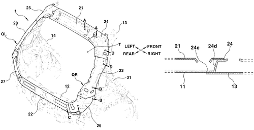
Hyundai Motor Company has recently unveiled a revolutionary new design for vehicle body rear portions. This innovative design features a tailgate opening portion that is designed to improve the torsional rigidity and durability performance of the entire body. By making this small but significant change, Hyundai has made it possible to make vehicles more reliable and longer-lasting than ever before. The tailgate opening portion also makes it easier to access the cargo area in any type of vehicle, from sedans to SUVs. With its improved strength and increased accessibility, this new feature from Hyundai will help drivers get more out of their vehicles for years to come.
A vehicle body rear portion may have a tailgate opening portion for improving torsional rigidity and durability performance of the vehicle body. This could be beneficial in preventing damage to the vehicle body caused by bending or twisting during operation.
US Patent 11535301
HONDA MOTOR CO., LTD.
Electric power generated by your old bike!
What is this invention?
Bicycle generator device and bicycle
A bicycle generator device was found,
Attached to the frame without a sound.
It had an annular rotational input member;
Connected it to the crank arm in a torque transmitting manner!
Using an existing bike, electricity could be bound!
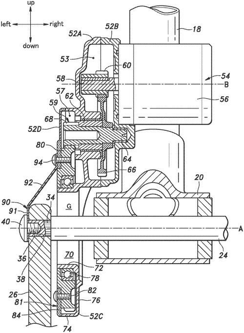
We are excited to introduce the latest innovation from Honda Motor Co. Ltd - a bicycle generator device and bicycle that can generate electric power with no damage to the tire of the bike! This revolutionary device is composed of a housing attached to the frame, an annular rotational input member connected to both the crankshaft and crank arm in a torque transmitting relationship, as well as a generator mounted on top. All these components work together so you can easily generate electricity by pedaling your existing bicycle without worrying about any wear and tear on your tires. This incredible new invention makes it simple for anyone to produce their own energy while having fun at the same time. Whether you’re looking for an eco-friendly way to get around town or just want a unique way to exercise, this innovative product from Honda Motor Co. Ltd has got you covered!
The patent describes a bicycle generator device that can be attached to a frame of a bicycle and used to generate electricity. The device comprises a housing, a generator attached to the housing, an annular rotational input member for rotationally driving the generator, and a connecting member connecting the rotational input member to the crankshaft or crank arm in a torque transmitting relationship. By using an existing bicycle, the device is able to generate electricity without impairing its durability.
US Patent 11535326
Honda Motor Co., Ltd.
A New S saddle Riding Vehicle Provides More Comfort and Control
What is this invention?
Saddle riding vehicle
A saddle riding vehicle was found
With a swing arm that did abound
The suspension had a valve part
On one side, it would start
To extend from the upper surface around
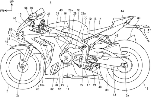
Honda Motor Co., Ltd. has just unveiled an amazing new saddle riding vehicle that is sure to revolutionize the way we ride. This revolutionary vehicle features a swing arm with front ends of arm sections and supporting a wheel supported by a pivot shaft, as well as an electronic control suspension between the pivot shaft and the arm sections. The suspension has a portion overlapping with the swing arm in side view of the vehicle, including a control valve section at its upper portion. What's more, this control valve section is disposed on one lateral side in regard of the vehicle width direction of the upper portion of the suspension and extends toward a vehicle width-directionally outer side from its side surface - providing superior stability and maneuverability for riders! With its innovative design, Honda's saddle riding vehicles are set to become must-haves for any serious rider looking for an enhanced experience on two wheels.
This saddle riding vehicle has a swing arm that supports the front ends of the arm sections and a wheel. The suspension has a control valve section on one side that extends out from the side surface of the upper portion.
US Patent 11535336
HONDA MOTOR CO., LTD.
Keep your sailing vessel within safe limits with our new sailing assisting system
What is this invention?
Sailing assisting system for vessel
A sailing assisting system was made,
To help a vessel sail in restricted trade.
Movable controlling devices, actuators and more,
Kept the hull within a certain shore.
The control unit warned the user of feeling strange,
So movable ranges were limited to not derange.
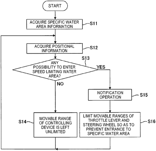
Are you a sailor looking for an easier way to navigate the open waters? Look no further than Honda Motor Co., Ltd.’s Sailing Assisting System for Vessels! This system is designed to provide sailing assistance when entering specific water areas where sailing is limited. It includes movable controlling devices such as shift and throttle controllers, steering devices, and trim switches that are driven by actuators like rotational shaft drive units, shaft drive units, and switch drive units. Furthermore, this system also has a control unit which executes notification operations and controls the actuators to limit the range of movement of these controlling devices if it detects that the vessel has entered a restricted area based on information from both its current position and the specific water area. With this system in place, sailors can rest assured knowing they won’t have any strange feelings while navigating their vessels in restricted areas with ease.
The patent describes a sailing assisting system that helps a vessel sail in restricted waters. The system includes movable controlling devices, actuators, and a control unit. If the hull of the vessel stays within a specific water area where sailing is limited, the control unit notifies the user and limits movable ranges of the controlling devices to prevent strange feeling for the steersman.
US Patent 11535348
The Boeing Company
Aerodynamic Body Includes Shockwave-Generating Waiverider Shape
What is this invention?
Aerodynamic body for supersonic speed
A body aerodynamic did need
An upper and lower surface indeed
The first axisymmetric, a part of the top
Mated with waverider shape to not stop
Resisting wind drag is its great deed!
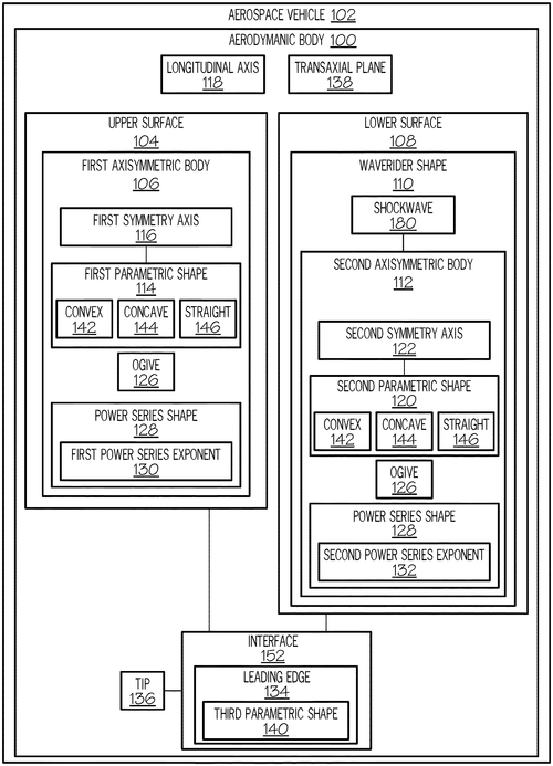
The Boeing Company has recently unveiled an incredible innovation in supersonic speed – a new aerodynamic body. This body is designed to reduce drag and increase lift, allowing for faster speeds than ever before. The upper surface of the body includes a first portion of a first axisymmetric shape, while the lower surface features a waverider shape that is derived from the shockwave generated by a second axisymmetric body. This unique design allows for more efficient air flow over the aircraft, resulting in higher speeds and better performance overall. With this innovative technology from The Boeing Company, we can look forward to even greater advancements in supersonic travel!
An aerodynamic body includes an upper surface and a lower surface. The upper surface includes a first portion of a first axisymmetric body. The lower surface is mated with the upper surface. The lower surface includes a waverider shape, which is derived from the shockwave generated by a second axisymmetric body. This allows the aerodynamic body to better resist wind drag.
US Patent 11535355
THE BOEING COMPANY
Adjustable Chines Deliver Increased Performance for Aircraft Nacelles
What is this invention?
Aircraft nacelles having adjustable chines
An aircraft nacelle with chines adjustable
To alter its wings in flight, quite sensible
The first segment aligned fore-aft direction
The second coplanar, precision perfection
For the pilot this craft is quite providential
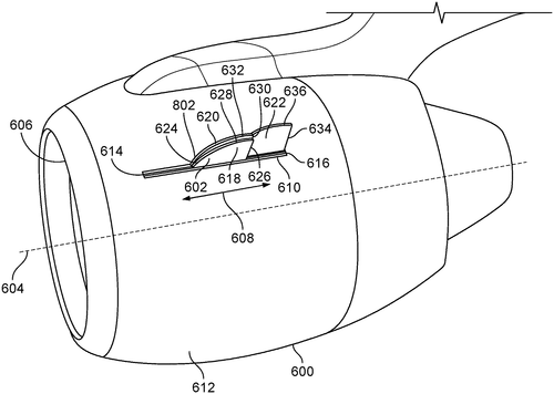
The Boeing Company has recently unveiled a revolutionary new invention – Aircraft nacelles with adjustable chines. This cutting-edge technology allows for more efficient aerodynamic performance and improved fuel efficiency, making it perfect for commercial aircrafts. The nacelle consists of two segments – a first segment oriented along the fore-aft direction which is translatable relative to the nacelle, and a second coplanar segment also oriented along the fore-aft direction. By adjusting these segments in relation to one another, air resistance can be minimized while still providing maximum thrust output from the engine. This adjustment also ensures that there is an optimal balance between drag and lift forces during flight, allowing for better fuel efficiency overall. This innovation from The Boeing Company will revolutionize how aircrafts are designed and operated in the future! With its ability to improve both aerodynamics and fuel efficiency, this technology promises to make flying faster, safer and more cost effective than ever before.
An aircraft nacelle with adjustable chines is described. The chine can be translatable relative to the nacelle along the fore-aft direction, and the chine can include a first segment oriented along that direction and a second segment oriented along the same direction but substantially coplanar with the first segment. This allows for precise adjustment of wing position in flight.
US Patent 11535362
The Boeing Company
Predictive Machine Prevents Vehicle Damage
What is this invention?
Process and machine for load alleviation
A machine was designed to protect
The aerospace part, a perfect project.
It used information known
To detect when it's thrown
And keep the part from breaking direct.
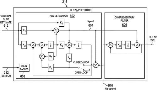
The Boeing Company has developed a revolutionary process and machine for load alleviation. The machine is designed to predict and preempt an undesired load or bending moment on parts of vehicles, such as aerospace vehicles, resulting from exogenous or control inputs. This advanced technology utilizes a predictor with an algorithm that can convert parameters from the state sensed upwind of the part into an estimated normal load on the part at a future time. Using this system, commands are derived to preempt the part from experiencing predicted loads or bending moments and actuated just prior to it happening in order to alleviate any potential damage caused by these forces. This innovative technology provides aircraft designers with unprecedented precision when designing their vehicles, allowing them to create reliable structures that will hold up under even extreme conditions. This new process and machine for load alleviation is yet another example of how The Boeing Company continues to push boundaries in aircraft design and engineering - making flying safer than ever before!
The process and machine described in the patent anticipates an undesired load or bending moment on a part of an aerospace vehicle, either due to external forces (exogenous) or as a result of the vehicle's own motion (control input). The machine uses known information about the state of the part upwind from the machine and/or maneuver data to predict a future state in which the part will experience a particular load or bending moment. If this prediction proves accurate, then a command is preempted before that event happens, thus preventing damage to the part.
US Patent 11535364
THE BOEING COMPANY
Air Duct System Provides Safe and Efficient Lighting
What is this invention?
Aircraft air duct system for transmitting electrical power and visible light
A duct system with light and waves
Had a reflective inner surface that saves
The emitter directs the RFs,
And antennas harvest power please,
Making it an efficient air device!
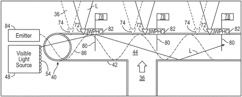
The Boeing Company has recently unveiled an incredible new invention: the Aircraft Air Duct System. This revolutionary system is designed to transmit both electrical power and visible light through a single air duct, making it easier than ever before to power aircrafts in flight. This advanced technology works by using a reflective inner surface of the air duct, allowing a visible light source to generate and direct visible light along this surface while an emitter directs radio frequency waves that are received by one or more antennas connected to corresponding power harvesting circuits. This process then converts the radio frequency waves into electrical power - all from within the same air duct! This groundbreaking innovation from The Boeing Company not only makes powering aircrafts simpler and more efficient, but also helps reduce weight on board as there is no need for multiple wiring systems for different types of energy transmission. With its potential applications ranging from aviation to construction, this Aircraft Air Duct System promises exciting possibilities for years to come!
The patent describes an air duct system that includes a main body, a visible light source, an emitter configured to emit radio frequency waves, and one or more antennas. The main body of the air duct defines a passageway having a reflective inner surface. The visible light source is configured to generate visible light that is directed along the reflective inner surface of the air duct. The emitter directs the radio frequency waves along the reflective inner surface of the air duct. The one or more antennas are each connected to a corresponding power harvesting circuit, where the radio frequency waves are received by the one or more antennas and are converted into electrical power by the corresponding power harvesting circuit.
US Patent 11535384
SUBARU CORPORATION
Electric Aircraft Powered by Electric Motor
What is this invention?
Electric aircraft and anti-icing apparatus for electric aircraft
An electric aircraft was made,
A propeller and motor displayed.
The controller inside the wing,
Was heat to the skin it did bring.
It's an efficient way to be swayed!
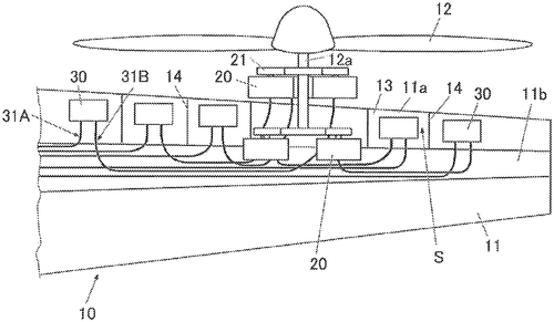
The future of aviation is here with SUBARU CORPORATION’s electric aircraft and anti-icing apparatus. This revolutionary invention takes the traditional propeller, electric motor, and controller combination to a whole new level by adding an innovative heating element that prevents ice from forming on the wings. The heat generated by the controller when it controls the motor is transmitted directly to the skin of the wing, ensuring that your aircraft stays safe during icy conditions. With this technology, you can fly worry-free knowing that your plane is protected from dangerous ice build up. So get ready for takeoff - SUBARU CORPORATION has made flying safer than ever before!
The patent describes an electric aircraft, which includes a propeller, an electric motor, and a controller. The electric motor is configured to supply power to the propeller. The controller is configured to control the electric motor. The controller is disposed inside a leading-edge portion of a wing to cause heat to be transmitted to a skin of the wing. The heat is generated by the controller when the controller controls the electric motor.
US Patent 11535385
The Boeing Company
The Ultimate Aircraft Maintenance Station:Platform Jacks That Adjust Easily Raise and Lower the Work Platform!
What is this invention?
Method and system for aircraft assembly and maintenance
A mobile work station was devised
To help with aircraft assembly and revised
The platform jacks can raise or lower
So access is no longer a bother
For those tasked with maintenance to be advised
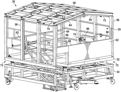
The Boeing Company has recently unveiled a revolutionary new system and method for aircraft assembly and maintenance. This system includes mobile work stations with adjustable platforms that can be lowered or raised, allowing for easy access to the aircraft during maintenance or assembly. The moveable base also supports the platform, making it easier than ever before to get up close and personal with your project. This innovative technology is perfect for any aviation enthusiast who needs quick access to their aircraft while performing routine maintenance or assembling a new plane from scratch. With its adjustable platform jacks, you can easily raise or lower the work station as needed - giving you full control over each step of the process. So whether you're an experienced professional looking for more efficient ways to service your fleet of planes, or just getting started in the world of aviation - this system from The Boeing Company is sure to make life easier!
The invention provides a mobile work station that can be used for performing assembly or maintenance on an aircraft. The work platform includes an accessway providing access to the work platform, and a moveable base supporting the work platform with one or more platform jacks that can adjustably raise and lower the work platform. This makes it easier to get onto and off of the work platform, which is useful for performing tasks such as assembly or maintenance on an aircraft.
US Patent 11535399
RICOH COMPANY, LTD.
New Sheet Guide Device Helps Keep Your Work Area Neat
What is this invention?
Sheet guiding device and image forming apparatus incorporating the sheet guiding device
A sheet guiding device was made,
With a cover unit and link swayed,
The swing guide moved to guide the sheets,
In retracted position it retreats,
And contact member makes the link sway indeed!
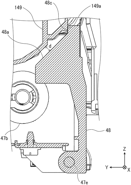
RICOH COMPANY, LTD. has recently unveiled a revolutionary sheet guiding device that is perfect for image forming apparatuses. This device includes a cover unit, swing guide, link member, and contact member that all work together to make sure sheets are guided correctly as they move through the apparatus. The cover unit opens on the housing of the image forming apparatus and allows the swing guide to move between a retracted position when closed and an open position when opened - allowing it to guide sheets properly. Additionally, the link member is held by the housing while its opposite end engages with the swing guide while in motion. Finally, there’s a contact member on the cover unit which contacts with the link member during closing movement of said cover unit - further rotating it into place for proper sheet guidance throughout your machine’s operation!
A sheet guiding device includes a cover unit, a swing guide, a link member, and a contact member. The cover unit is configured to be openably disposed on the housing of an image forming apparatus. The swing guide is configured to move between a guide position at which the swing guide is open to guide a sheet and a retracted position at which the swingguide is closed. The swingguide is configured to move from the retracted position to the guideposition along with closing movement of the cover unit. The link member has one end configured to be held by the housing and an opposite end engaged withthe swing guide. The contact member is disposed on the cover unit.
US Patent 11535467